Hitachi C12LSH Instruction Manual - Page 29
r-lZ
 |
UPC - 717709010338
View all Hitachi C12LSH manuals
Add to My Manuals
Save this manual to your list of manuals |
Page 29 highlights
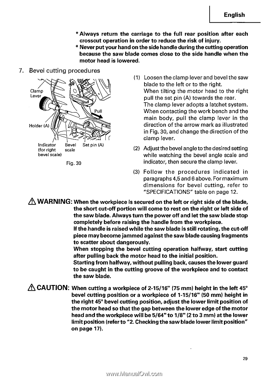
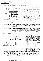
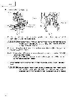
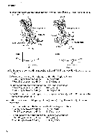
English * Always return the carriage to the full rear position after each crosscut operation in order to reduce the risk of injury. * Never put your hand on the side handle during the cutting operation because the saw blade comes close to the side handle when the motor head is lowered. 7. Bevel cutting procedures Clamp Lever M 0 Holder (A) Pull 4r-lZ Indicator Bevel Set pin (A) (for right scale bevel scale) Fig. 30 (1) Loosen the clamp lever and bevel the saw blade to the left or to the right. When tilting the motor head to the right pull the set pin (A) towards the rear. The clamp lever adopts a latchet system. When contacting the work bench and the main body, pull the clamp lever in the direction of the arrow mark as illustrated in Fig. 30, and change the direction of the clamp lever. (2) Adjust the bevel angle to the desired setting while watching the bevel angle scale and indicator, then secure the clamp lever. (3) Follow the procedures indicated in paragraphs 4,5 and 6 above. For maximum dimensions for bevel cutting, refer to "SPECIFICATIONS" table on page 12. WARNING: When the workpiece is secured on the left or right side of the blade, the short cut-off portion will come to rest on the right or left side of the saw blade. Always turn the power off and let the saw blade stop completely before raising the handle from the workpiece. If the handle is raised while the saw blade is still rotating, the cut-off piece may become jammed against the saw blade causing fragments to scatter about dangerously. When stopping the bevel cutting operation halfway, start cutting after pulling back the motor head to the initial position. Starting from halfway, without pulling back, causes the lower guard to be caught in the cutting groove of the workpiece and to contact the saw blade. CAUTION: When cutting a workpiece of 2-15/16" (75 mm) height in the left 45° bevel cutting position or a workpiece of 1-15/16" (50 mm) height in the right 45° bevel cutting position, adjust the lower limit position of the motor head so that the gap between the lower edge of the motor head and the workpiece will be 5/64" to 1/8" (2 to 3 mm) at the lower limit position (refer to "2. Checking the saw blade lower limit position" on page 17). 29
-
 1
1 -
2
-
3
-
4
-
5
-
6
-
7
-
8
-
9
-
10
-
11
-
12
-
13
-
14
-
15
-
16
-
17
-
18
-
19
-
20
-
21
-
22
-
23
-
 24
24 -
 25
25 -
 26
26 -
 27
27 -
 28
28 -
 29
29 -
 30
30 -
 31
31 -
 32
32 -
 33
33 -
 34
34 -
35
-
36
-
37
-
38
-
39
-
40
-
41
-
42
 |
 |