Hitachi C12LSH Instruction Manual - Page 17
Furthermore
 |
UPC - 717709010338
View all Hitachi C12LSH manuals
Add to My Manuals
Save this manual to your list of manuals |
Page 17 highlights
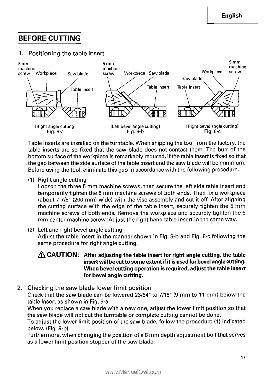
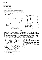
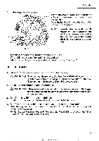
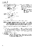
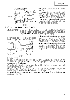
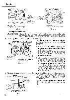
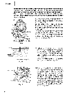
English BEFORE CUTTING 1. Positioning the table insert 5mm machine screw Workpiece Saw blade 5mm machine screw Workpiece Saw blade Table insert Table insert Workpiece Saw blade Table insert 5mm machine screw [Right angle cutting] Fig. 8-a [Left bevel angle cuff ng] Fig. 8-b [Right bevel angle cutting] Fig. 8-c Table inserts are installed on the turntable. When shipping the tool from the factory, the table inserts are so fixed that the saw blade does not contact them. The burr of the bottom surface of the workpiece is remarkably reduced, if the table insert is fixed so that the gap between the side surface of the table insert and the saw blade will be minimum. Before using the tool, eliminate this gap in accordance with the following procedure. (1) Right angle cutting Loosen the three 5 mm machine screws, then secure the left side table insert and temporarily tighten the 5 mm machine screws of both ends. Then fix a workpiece (about 7-7/8" (200 mm) wide) with the vise assembly and cut it off. After aligning the cutting surface with the edge of the table insert, securely tighten the 5 mm machine screws of both ends. Remove the workpiece and securely tighten the 5 mm center machine screw. Adjust the right hand table insert in the same way. (2) Left and right bevel angle cutting Adjust the table insert in the manner shown in Fig. 8-b and Fig. 8-c following the same procedure for right angle cutting. Q CAUTION: After adjusting the table insert for right angle cutting, the table insert will be cut to some extent if it is used for bevel angle cutting. When bevel cutting operation is required, adjust the table insert for bevel angle cutting. 2. Checking the saw blade lower limit position Check that the saw blade can be lowered 23/64" to 7/16" (9 mm to 11 mm) below the table insert as shown in Fig. 9-a. When you replace a saw blade with a new one, adjust the lower limit position so that the saw blade will not cut the turntable or complete cutting cannot be done. To adjust the lower limit position of the saw blade, follow the procedure (1) indicated below. (Fig. 9-b) Furthermore, when changing the position of a 8 mm depth adjustment bolt that serves as a lower limit position stopper of the saw blade. 17
-
 1
1 -
2
-
3
-
4
-
5
-
6
-
7
-
8
-
9
-
10
-
11
-
 12
12 -
 13
13 -
 14
14 -
 15
15 -
 16
16 -
 17
17 -
 18
18 -
 19
19 -
 20
20 -
 21
21 -
 22
22 -
23
-
24
-
25
-
26
-
27
-
28
-
29
-
30
-
31
-
32
-
33
-
34
-
35
-
36
-
37
-
38
-
39
-
40
-
41
-
42
 |
 |