Hitachi C12LSH Instruction Manual - Page 36
blade
 |
UPC - 717709010338
View all Hitachi C12LSH manuals
Add to My Manuals
Save this manual to your list of manuals |
Page 36 highlights
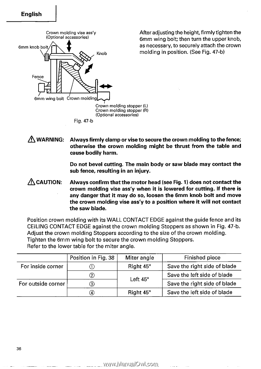
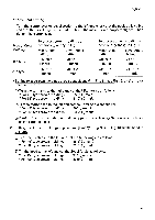
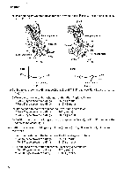
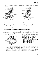
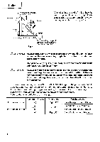
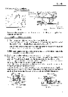
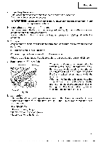
English Crown molding vise ass'y (Optional accessories) 6mm knob bolt Knob After adjusting the height,firmly tighten the 6mm wing bolt; then turn the upper knob, as necessary, to securely attach the crown molding in position. (See Fig. 47-b) Fence 6mm wing bolt Crown molding Crown molding stopper (L) Crown molding stopper (R) (Optional accessories) Fig. 47-b & WARNING: Always firmly clamp or vise to secure the crown molding to the fence; otherwise the crown molding might be thrust from the table and cause bodily harm. Do not bevel cutting. The main body or saw blade may contact the sub fence, resulting in an injury. &CAUTION: Always confirm that the motor head (see Fig. 1) does not contact the crown molding vise ass'y when it is lowered for cutting. If there is any danger that it may do so, loosen the 6mm knob bolt and move the crown molding vise ass'y to a position where it will not contact the saw blade. Position crown molding with its WALL CONTACT EDGE against the guide fence and its CEILING CONTACT EDGE against the crown molding Stoppers as shown in Fig. 47-b. Adjust the crown molding Stoppers according to the size of the crown molding. Tighten the 6mm wing bolt to secure the crown molding Stoppers. Refer to the lower table for the miter angle. Position in Fig. 38 For inside corner ® © For outside corner C) ® Miter angle Right 45° Left 45° Right 45° Finished piece Save the right side of blade Save the left side of blade Save the right side of blade Save the left side of blade 36
-
 1
1 -
2
-
3
-
4
-
5
-
6
-
7
-
8
-
9
-
10
-
11
-
12
-
13
-
14
-
15
-
16
-
17
-
18
-
19
-
20
-
21
-
22
-
23
-
24
-
25
-
26
-
27
-
28
-
29
-
30
-
 31
31 -
 32
32 -
 33
33 -
 34
34 -
 35
35 -
 36
36 -
 37
37 -
 38
38 -
 39
39 -
 40
40 -
 41
41 -
42
 |
 |