Hitachi C12LSH Instruction Manual - Page 19
&warning
 |
UPC - 717709010338
View all Hitachi C12LSH manuals
Add to My Manuals
Save this manual to your list of manuals |
Page 19 highlights
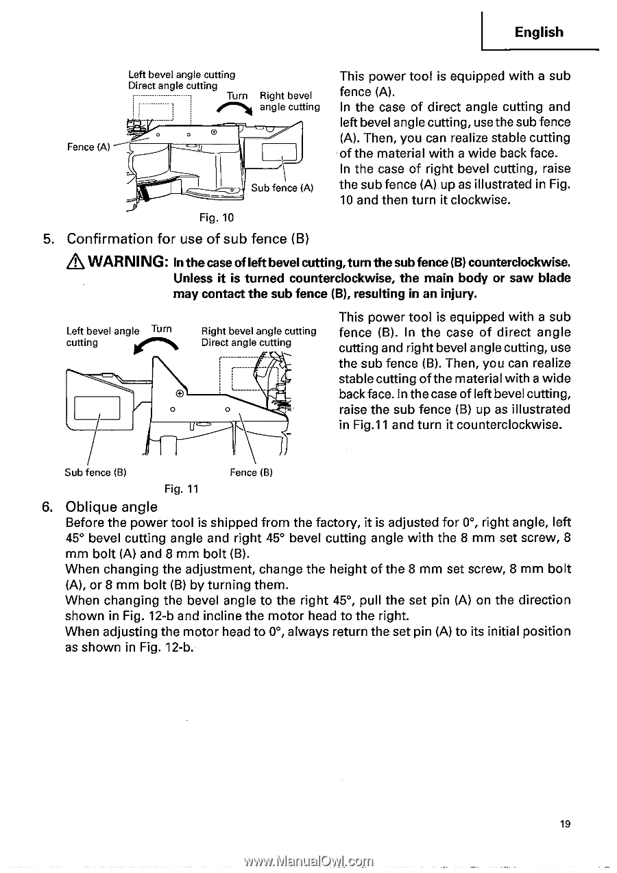
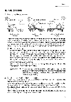
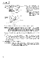
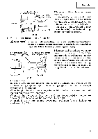
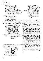
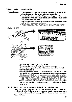
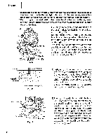
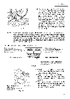
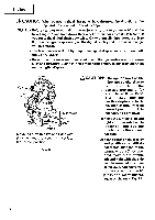
English Fence (A) Left bevel angle cutting Direct angle cutting Turn Right bevel angle cutting O IJ Sub fence (A) Fig. 10 This power tool is equipped with a sub fence (A). In the case of direct angle cutting and left bevel angle cutting, use the sub fence (A). Then, you can realize stable cutting of the material with a wide back face. In the case of right bevel cutting, raise the sub fence (A) up as illustrated in Fig. 10 and then turn it clockwise. 5. Confirmation for use of sub fence (B) &WARNING: In the case ofleftbevel cutting,turn the sub fence (B) counterclockwise. Unless it is turned counterclockwise, the main body or saw blade may contact the sub fence (B), resulting in an injury. Left bevel angle Turn cutting ea' 0 Right bevel angle cutting Direct angle cutting r fry This power tool is equipped with a sub fence (B). In the case of direct angle cutting and right bevel angle cutting, use the sub fence (B). Then, you can realize stable cutting of the material with a wide back face. In the case of left bevel culling, raise the sub fence (B) up as illustrated in Fig.11 and turn it counterclockwise. Sub fence (B) Fence (B) Fig. 11 6. Oblique angle Before the power tool is shipped from the factory, it is adjusted for 0°, right angle, left 45° bevel cutting angle and right 45° bevel cutting angle with the 8 mm set screw, 8 mm bolt (A) and 8 mm bolt (B). When changing the adjustment, change the height of the 8 mm set screw, 8 mm bolt (A), or 8 mm bolt (B) by turning them. When changing the bevel angle to the right 45°, pull the set pin (A) on the direction shown in Fig. 12-b and incline the motor head to the right. When adjusting the motor head to 0°, always return the set pin (A) to its initial position as shown in Fig. 12-b. 19
-
 1
1 -
2
-
3
-
4
-
5
-
6
-
7
-
8
-
9
-
10
-
11
-
12
-
13
-
 14
14 -
 15
15 -
 16
16 -
 17
17 -
 18
18 -
 19
19 -
 20
20 -
 21
21 -
 22
22 -
 23
23 -
 24
24 -
25
-
26
-
27
-
28
-
29
-
30
-
31
-
32
-
33
-
34
-
35
-
36
-
37
-
38
-
39
-
40
-
41
-
42
 |
 |