Hitachi C12LSH Instruction Manual - Page 20
operation.
 |
UPC - 717709010338
View all Hitachi C12LSH manuals
Add to My Manuals
Save this manual to your list of manuals |
Page 20 highlights
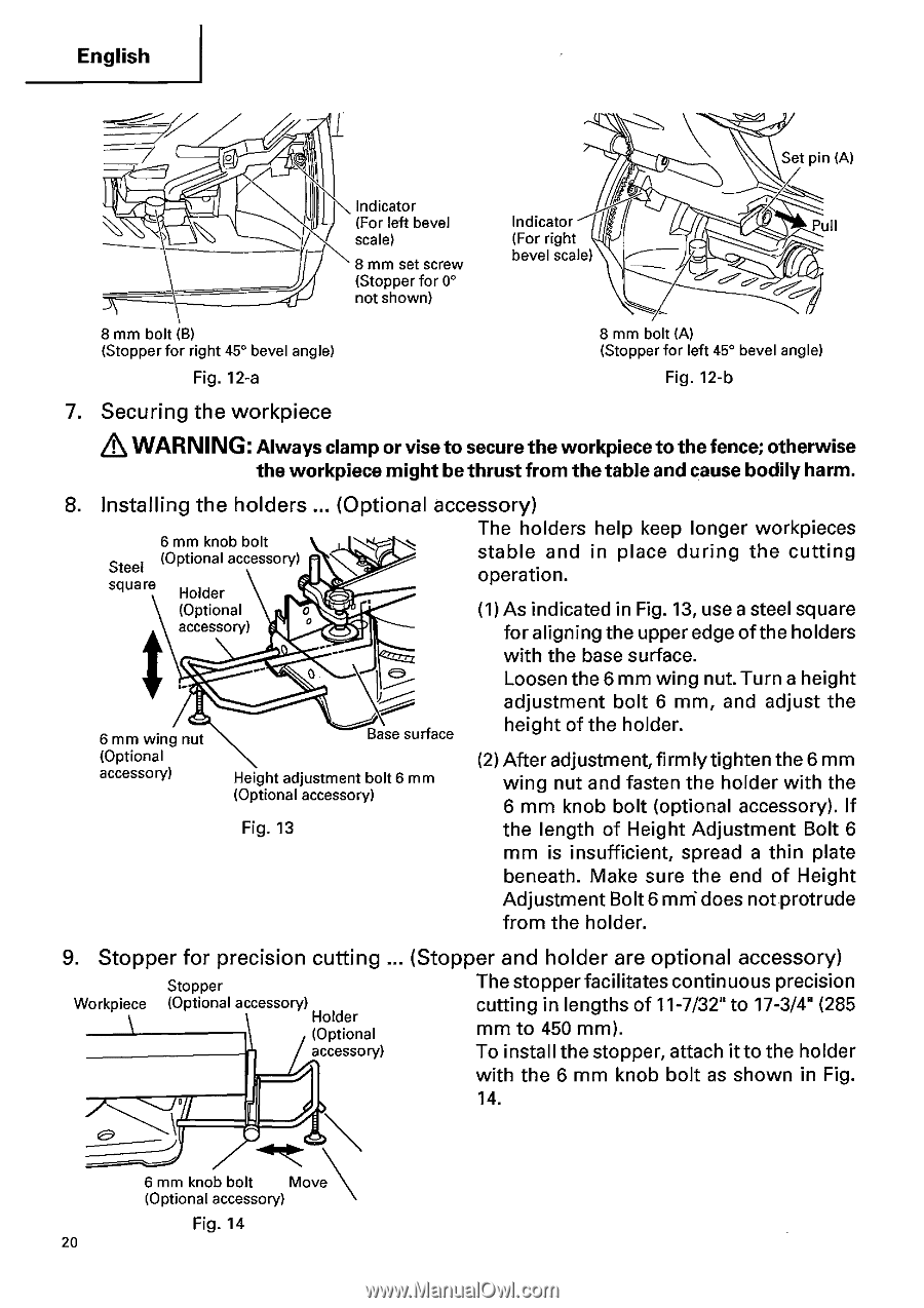
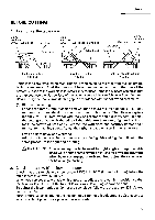
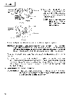
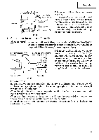
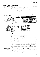
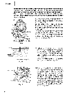
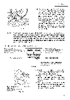
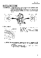
English O Set pin (A) Indicator (For left bevel scale) 8 mm set screw (Stopper for 0° not shown) Indicator (For right bevel scale) Pull 00 8 mm bolt (B) (Stopper for right 45° bevel angle) Fig. 12-a 8 mm bolt (A) (Stopper for left 45° bevel angle) Fig. 12-b 7. Securing the workpiece WARNING: Always clamp or vise to secure the workpiece to the fence; otherwise the workpiece might be thrust from the table and cause bodily harm. 8. Installing the holders ... (Optional accessory) 6 mm knob bolt Steel (Optional accessory) square Holder (Optional 0 accessory) 0 The holders help keep longer workpieces stable and in place during the cutting operation. (1) As indicated in Fig. 13, use a steel square for aligning the upper edge of the holders with the base surface. Loosen the 6 mm wing nut. Turn a height adjustment bolt 6 mm, and adjust the 6 mm wing nut (Optional accessory) Base surface Height adjustment bolt 6 mm (Optional accessory) height of the holder. (2) After adjustment,firmly tighten the 6 mm wing nut and fasten the holder with the 6 mm knob bolt (optional accessory). If Fig. 13 the length of Height Adjustment Bolt 6 mm is insufficient, spread a thin plate beneath. Make sure the end of Height Adjustment Bolt 6 mni does not protrude from the holder. 9. Stopper for precision cutting ... (Stopper and holder are optional accessory) Stopper The stopper facilitates continuous precision Workpiece (Optional accessory) Holder (Optional accessory) cutting in lengths of 11-7/32" to 17-3/4" (285 mm to 450 mm). To install the stopper, attach it to the holder with the 6 mm knob bolt as shown in Fig. 14. 6 mm knob bolt Move (Optional accessory) Fig. 14 20
-
 1
1 -
2
-
3
-
4
-
5
-
6
-
7
-
8
-
9
-
10
-
11
-
12
-
13
-
14
-
 15
15 -
 16
16 -
 17
17 -
 18
18 -
 19
19 -
 20
20 -
 21
21 -
 22
22 -
 23
23 -
 24
24 -
 25
25 -
26
-
27
-
28
-
29
-
30
-
31
-
32
-
33
-
34
-
35
-
36
-
37
-
38
-
39
-
40
-
41
-
42
 |
 |