Hitachi C12LSH Instruction Manual - Page 26
English, &WARNING, &CAUTION
 |
UPC - 717709010338
View all Hitachi C12LSH manuals
Add to My Manuals
Save this manual to your list of manuals |
Page 26 highlights
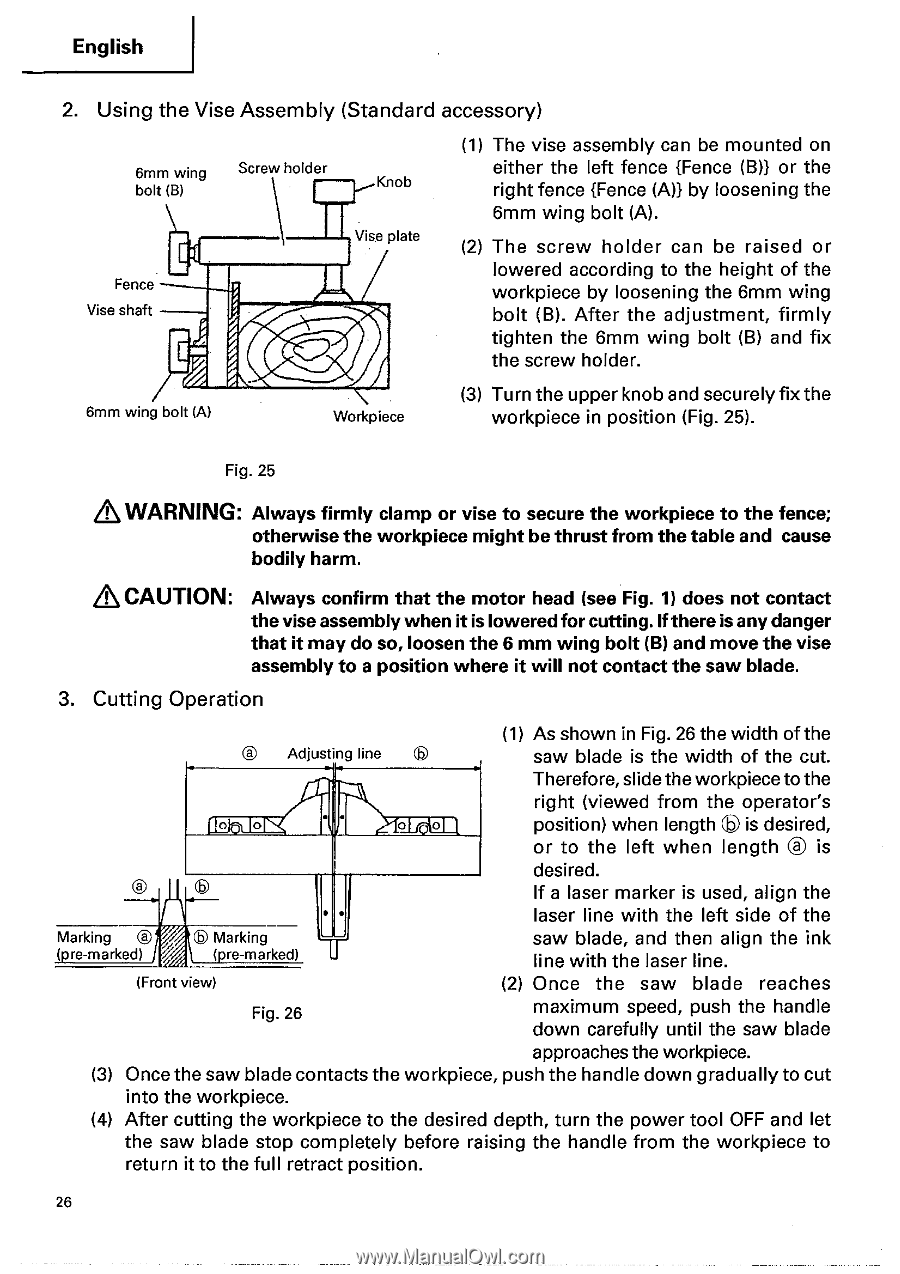
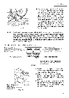
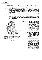
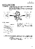
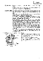
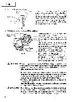
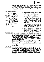
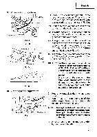
English 2. Using the Vise Assembly (Standard accessory) 6mm wing bolt (B) Screw holder Knob Vise plate Fence Vise shaft (1) The vise assembly can be mounted on either the left fence {Fence (B)) or the right fence {Fence (A)) by loosening the 6mm wing bolt (A). (2) The screw holder can be raised or lowered according to the height of the workpiece by loosening the 6mm wing bolt (B). After the adjustment, firmly tighten the 6mm wing bolt (B) and fix the screw holder. 6mm wing bolt (A) Workpiece (3) Turn the upper knob and securely fix the workpiece in position (Fig. 25). Fig. 25 &WARNING: Always firmly clamp or vise to secure the workpiece to the fence; otherwise the workpiece might be thrust from the table and cause bodily harm. &CAUTION: Always confirm that the motor head (see Fig. 1) does not contact the vise assembly whenit is lowered for cutting.If there is any danger that it may do so, loosen the 6 mm wing bolt (B) and move the vise assembly to a position where it will not contact the saw blade. 3. Cutting Operation (1) As shown in Fig. 26 the width of the Adjusting line saw blade is the width of the cut. Therefore, slide the workpiece to the right (viewed from the operator's 0 0 0 position) when length is desired, or to the left when length ® is desired. If a laser marker is used, align the • laser line with the left side of the Marking ® , (.re-marked) Marking (.re-marked) I saw blade, and then align the ink line with the laser line. (Front view) (2) Once the saw blade reaches Fig. 26 maximum speed, push the handle down carefully until the saw blade approaches the workpiece. (3) Once the saw blade contacts the workpiece, push the handle down gradually to cut into the workpiece. (4) After cutting the workpiece to the desired depth, turn the power tool OFF and let the saw blade stop completely before raising the handle from the workpiece to return it to the full retract position. 26
-
 1
1 -
2
-
3
-
4
-
5
-
6
-
7
-
8
-
9
-
10
-
11
-
12
-
13
-
14
-
15
-
16
-
17
-
18
-
19
-
20
-
 21
21 -
 22
22 -
 23
23 -
 24
24 -
 25
25 -
 26
26 -
 27
27 -
 28
28 -
 29
29 -
 30
30 -
 31
31 -
32
-
33
-
34
-
35
-
36
-
37
-
38
-
39
-
40
-
41
-
42
 |
 |