IBM 2658 Hardware Maintenance Manual - Page 89
Fan Disassembly, Sink Module, CPU or System Board is replaced.
 |
UPC - 087944841135
View all IBM 2658 manuals
Add to My Manuals
Save this manual to your list of manuals |
Page 89 highlights
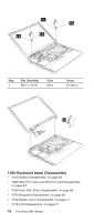
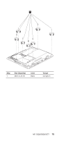
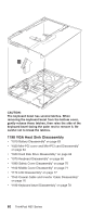
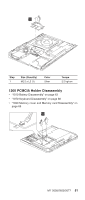
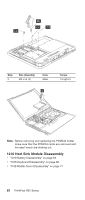
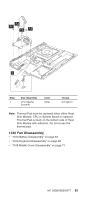
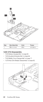
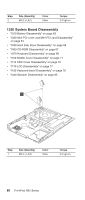
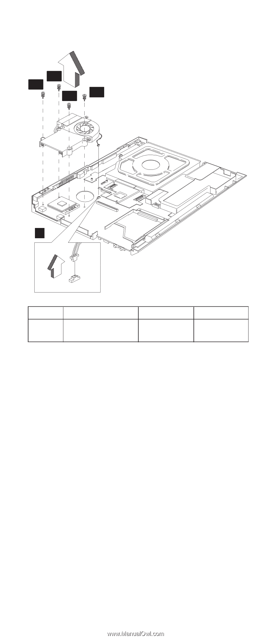
1a 1c 1b 1d 1 Step 1 Size (Quantity) CPU Special Screw(4) Color Silver Torque 2.5 kgf-cm Note: Thermal Pad must be replaced when either Heat Sink Module, CPU or System Board is replaced. Thermal Pad is stuck on the bottom side of Heat Sink Module with adhesive. Do not re-use the thermal pad. 1220 Fan Disassembly v "1010 Battery Disassembly" on page 63 v "1070 Keyboard Disassembly" on page 68 v "1100 Middle Cover Disassembly" on page 71 MT 2658/2659/2677 83
-
 1
1 -
2
-
3
-
4
-
5
-
6
-
7
-
8
-
9
-
10
-
11
-
12
-
13
-
14
-
15
-
16
-
17
-
18
-
19
-
20
-
21
-
22
-
23
-
24
-
25
-
26
-
27
-
28
-
29
-
30
-
31
-
32
-
33
-
34
-
35
-
36
-
37
-
38
-
39
-
40
-
41
-
42
-
43
-
44
-
45
-
46
-
47
-
48
-
49
-
50
-
51
-
52
-
53
-
54
-
55
-
56
-
57
-
58
-
59
-
60
-
61
-
62
-
63
-
64
-
65
-
66
-
67
-
68
-
69
-
70
-
71
-
72
-
73
-
74
-
75
-
76
-
77
-
78
-
79
-
80
-
81
-
82
-
83
-
 84
84 -
 85
85 -
 86
86 -
 87
87 -
 88
88 -
 89
89 -
 90
90 -
 91
91 -
 92
92 -
 93
93 -
 94
94 -
95
-
96
-
97
-
98
-
99
-
100
-
101
-
102
-
103
-
104
-
105
-
106
-
107
-
108
-
109
-
110
-
111
-
112
-
113
-
114
-
115
-
116
-
117
-
118
-
119
-
120
-
121
-
122
-
123
-
124
-
125
-
126
-
127
-
128
-
129
-
130
-
131
-
132
-
133
-
134
-
135
-
136
-
137
-
138
-
139
-
140
-
141
-
142
-
143
-
144
-
145
-
146
-
147
-
148
-
149
-
150
-
151
-
152
-
153
-
154
-
155
-
156
-
157
-
158
-
159
-
160
-
161
-
162
-
163
-
164
-
165
-
166
-
167
-
168
-
169
-
170
-
171
-
172
-
173
-
174
-
175
-
176
-
177
-
178
-
179
-
180
-
181
-
182
-
183
-
184
-
185
-
186
-
187
-
188
-
189
-
190
-
191
-
192
-
193
-
194
-
195
-
196
-
197
-
198
-
199
-
200
-
201
-
202
-
203
-
204
-
205
-
206
-
207
-
208
-
209
-
210
-
211
-
212
-
213
-
214
-
215
-
216
-
217
-
218
-
219
-
220
-
221
-
222
-
223
-
224
-
225
-
226
-
227
-
228
-
229
-
230
-
231
-
232
-
233
-
234
-
235
-
236
-
237
-
238
-
239
-
240
-
241
-
242
-
243
-
244
-
245
-
246
-
247
-
248
 |
 |
1
1a
1b
1c
1d
Step
Size (Quantity)
Color
Torque
1
CPU Special
Screw(4)
Silver
2.5 kgf-cm
Note:
Thermal Pad must be replaced when either Heat
Sink Module, CPU or System Board is replaced.
Thermal Pad is stuck on the bottom side of Heat
Sink Module with adhesive. Do not re-use the
thermal pad.
1220 Fan Disassembly
v
“
1010 Battery Disassembly
”
on page 63
v
“
1070 Keyboard Disassembly
”
on page 68
v
“
1100 Middle Cover Disassembly
”
on page 71
MT 2658/2659/2677
83