IBM 2658 Hardware Maintenance Manual - Page 93
I/O Port Bracket Disassembly, Module, CPU or System Board is replaced. Thermal
 |
UPC - 087944841135
View all IBM 2658 manuals
Add to My Manuals
Save this manual to your list of manuals |
Page 93 highlights
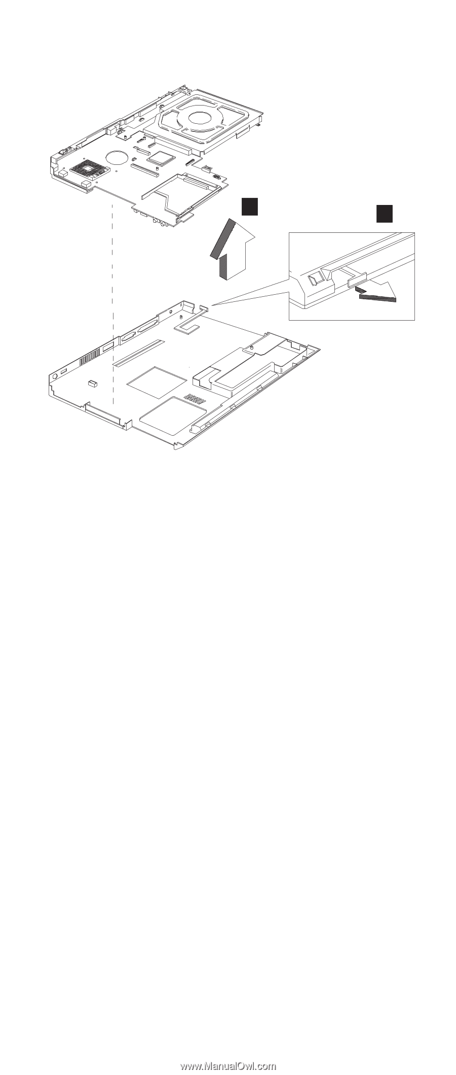
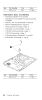
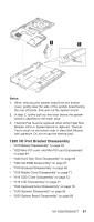
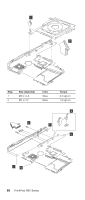
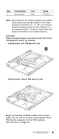
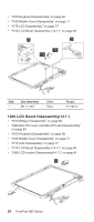
3 2 Notes: 1. When removing the system board from the bottom cover, gently raise the side of the system board facing the rear I/O ports; then pull out the system board. 2. In step 2, further pull out this latch before the system board is attached to the lower case. 3. Thermal Pad must be replaced when either Heat Sink Module, CPU or System Board is replaced. Thermal Pad is stuck on the bottom side of Heat Sink Module with adhesive. Do not re-use the thermal pad. 1260 I/O Port Bracket Disassembly v "1010 Battery Disassembly" on page 63 v "1020 Mini-PCI cover and Mini-PCI card Disassembly" on page 64 v "1040 Hard Disk Drive Disassembly" on page 66 v "1060 CD-ROM Disassembly" on page 67 v "1070 Keyboard Disassembly" on page 68 v "1100 Middle Cover Disassembly" on page 71 v "1110 CDC Cover Disassembly" on page 72 v "1170 LCD Disassembly" on page 77 v "1180 Keyboard bezel Disassembly" on page 78 v "1240 Speaker Disassembly" on page 85 v "1250 System Board Disassembly" on page 86 MT 2658/2659/2677 87
-
 1
1 -
2
-
3
-
4
-
5
-
6
-
7
-
8
-
9
-
10
-
11
-
12
-
13
-
14
-
15
-
16
-
17
-
18
-
19
-
20
-
21
-
22
-
23
-
24
-
25
-
26
-
27
-
28
-
29
-
30
-
31
-
32
-
33
-
34
-
35
-
36
-
37
-
38
-
39
-
40
-
41
-
42
-
43
-
44
-
45
-
46
-
47
-
48
-
49
-
50
-
51
-
52
-
53
-
54
-
55
-
56
-
57
-
58
-
59
-
60
-
61
-
62
-
63
-
64
-
65
-
66
-
67
-
68
-
69
-
70
-
71
-
72
-
73
-
74
-
75
-
76
-
77
-
78
-
79
-
80
-
81
-
82
-
83
-
84
-
85
-
86
-
87
-
 88
88 -
 89
89 -
 90
90 -
 91
91 -
 92
92 -
 93
93 -
 94
94 -
 95
95 -
 96
96 -
 97
97 -
 98
98 -
99
-
100
-
101
-
102
-
103
-
104
-
105
-
106
-
107
-
108
-
109
-
110
-
111
-
112
-
113
-
114
-
115
-
116
-
117
-
118
-
119
-
120
-
121
-
122
-
123
-
124
-
125
-
126
-
127
-
128
-
129
-
130
-
131
-
132
-
133
-
134
-
135
-
136
-
137
-
138
-
139
-
140
-
141
-
142
-
143
-
144
-
145
-
146
-
147
-
148
-
149
-
150
-
151
-
152
-
153
-
154
-
155
-
156
-
157
-
158
-
159
-
160
-
161
-
162
-
163
-
164
-
165
-
166
-
167
-
168
-
169
-
170
-
171
-
172
-
173
-
174
-
175
-
176
-
177
-
178
-
179
-
180
-
181
-
182
-
183
-
184
-
185
-
186
-
187
-
188
-
189
-
190
-
191
-
192
-
193
-
194
-
195
-
196
-
197
-
198
-
199
-
200
-
201
-
202
-
203
-
204
-
205
-
206
-
207
-
208
-
209
-
210
-
211
-
212
-
213
-
214
-
215
-
216
-
217
-
218
-
219
-
220
-
221
-
222
-
223
-
224
-
225
-
226
-
227
-
228
-
229
-
230
-
231
-
232
-
233
-
234
-
235
-
236
-
237
-
238
-
239
-
240
-
241
-
242
-
243
-
244
-
245
-
246
-
247
-
248
 |
 |