IBM 4840 Service Guide - Page 9

IBM 4840 - SurePOS 500 - 32 MB RAM Manual

Page 9 highlights

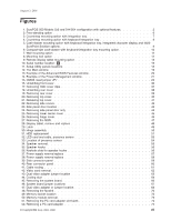
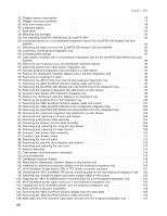
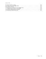
August 3, 2006 Figures 1. SurePOS 500 Models 5x3 and 544/564 configuration with optional features 2 2. Free-standing option 6 3. Countertop mounting option with integration tray 7 4. Countertop mounting option with keyboard-integration tray 8 5. Cash-drawer mounting option with keyboard integration tray, integrated character display and 4820 SurePoint Solution options 9 6. Compact-size cash-drawer with keyboard-integration tray mounting option 10 7. Wall mounting option 11 8. Mounting foot option 12 9. Remote display tablet mounting option 13 10. Serial number location: A 16 11. Setup Utility panels locations 18 12. The Main window 19 13. Example of the Advanced BIOS Features window 20 14. Example of the Power Management window 21 15. CMOS reset jumper JP7 23 16. Unlatching front cover 36 17. Removing HDD cover clips 37 18. Unlatching rear cover 38 19. Removing rear cover 39 20. Removing top cover 40 21. Releasing top cover 41 22. Removing side covers 42 23. Side panel door location 43 24. Removing side panel door only 44 25. Removing tower center cover 45 26. Removing hinge cover 46 27. Removing the MSR 47 28. Display tablet, remove and replace 48 29. Latch 49 30. Hinge assembly 50 31. HDD replacement 51 32. LED card and cable, presence sensor 53 33. Location of presence sensor 54 34. Speaker removal 55 35. Speaker hooks 56 36. Keyhole slots for speaker hooks 56 37. Power supply remove/replace 57 38. Power supply remove/replace 58 39. Side connector panel 59 40. Rear connector panel 60 41. Cable routing 61 42. Video card removal 62 43. Dual video adapter jumper location 63 44. Cooling duct 64 45. Removing the system board 66 46. System board jumper locations 67 47. Dual video adapter or jumper location 68 48. Removing the fansink 70 49. Memory socket location 72 50. Memory module removal 73 51. Removing the PC card adapter slot blank 74 52. Removing a PC card adapter 75 © Copyright IBM Corp. 2004, 2006 vii

  • 1
  • 2
  • 3
  • 4
  • 5
  • 6
  • 7
  • 8
  • 9
  • 10
  • 11
  • 12
  • 13
  • 14
  • 15
  • 16
  • 17
  • 18
  • 19
  • 20
  • 21
  • 22
  • 23
  • 24
  • 25
  • 26
  • 27
  • 28
  • 29
  • 30
  • 31
  • 32
  • 33
  • 34
  • 35
  • 36
  • 37
  • 38
  • 39
  • 40
  • 41
  • 42
  • 43
  • 44
  • 45
  • 46
  • 47
  • 48
  • 49
  • 50
  • 51
  • 52
  • 53
  • 54
  • 55
  • 56
  • 57
  • 58
  • 59
  • 60
  • 61
  • 62
  • 63
  • 64
  • 65
  • 66
  • 67
  • 68
  • 69
  • 70
  • 71
  • 72
  • 73
  • 74
  • 75
  • 76
  • 77
  • 78
  • 79
  • 80
  • 81
  • 82
  • 83
  • 84
  • 85
  • 86
  • 87
  • 88
  • 89
  • 90
  • 91
  • 92
  • 93
  • 94
  • 95
  • 96
  • 97
  • 98
  • 99
  • 100
  • 101
  • 102
  • 103
  • 104
  • 105
  • 106
  • 107
  • 108
  • 109
  • 110
  • 111
  • 112
  • 113
  • 114
  • 115
  • 116
  • 117
  • 118
  • 119
  • 120
  • 121
  • 122
  • 123
  • 124
  • 125
  • 126
  • 127
  • 128
  • 129
  • 130
  • 131
  • 132
  • 133
  • 134
  • 135
  • 136
  • 137
  • 138
  • 139
  • 140
  • 141
  • 142
  • 143
  • 144
  • 145
  • 146
  • 147
  • 148
  • 149
  • 150
  • 151
  • 152
  • 153
  • 154
  • 155
  • 156
  • 157
  • 158
  • 159
  • 160
  • 161
  • 162
  • 163
  • 164
  • 165
  • 166
  • 167
  • 168
  • 169
  • 170
  • 171
  • 172
  • 173
  • 174
  • 175
  • 176
  • 177
  • 178
  • 179
  • 180
  • 181
  • 182
  • 183
  • 184
  • 185
  • 186
  • 187
  • 188
  • 189
  • 190
  • 191
  • 192
  • 193
  • 194
  • 195
  • 196
  • 197
  • 198
  • 199
  • 200
  • 201
  • 202
  • 203
  • 204
  • 205
  • 206
  • 207
  • 208
  • 209
  • 210
  • 211
  • 212
  • 213
  • 214
  • 215
  • 216
  • 217
  • 218
  • 219
  • 220
  • 221
  • 222
  • 223
  • 224
  • 225
  • 226
  • 227
  • 228
  • 229
  • 230
  • 231
  • 232
  • 233
  • 234
  • 235
  • 236
  • 237
  • 238
  • 239
  • 240
  • 241
  • 242
  • 243
  • 244
  • 245
  • 246
  • 247
  • 248
  • 249
  • 250
  • 251
  • 252
  • 253
  • 254
  • 255
  • 256
  • 257
  • 258

Figures
1.
SurePOS
500
Models
5x3
and
544/564
configuration
with
optional
features
.
.
.
.
.
.
.
.
.
.2
2.
Free-standing
option
.
.
.
.
.
.
.
.
.
.
.
.
.
.
.
.
.
.
.
.
.
.
.
.
.
.
.
.
.
.6
3.
Countertop
mounting
option
with
integration
tray
.
.
.
.
.
.
.
.
.
.
.
.
.
.
.
.
.
.
.
.7
4.
Countertop
mounting
option
with
keyboard-integration
tray
.
.
.
.
.
.
.
.
.
.
.
.
.
.
.
.8
5.
Cash-drawer
mounting
option
with
keyboard
integration
tray,
integrated
character
display
and
4820
SurePoint
Solution
options
.
.
.
.
.
.
.
.
.
.
.
.
.
.
.
.
.
.
.
.
.
.
.
.
.
.
.
.9
6.
Compact-size
cash-drawer
with
keyboard-integration
tray
mounting
option
.
.
.
.
.
.
.
.
.
. 10
7.
Wall
mounting
option
.
.
.
.
.
.
.
.
.
.
.
.
.
.
.
.
.
.
.
.
.
.
.
.
.
.
.
.
. 11
8.
Mounting
foot
option
.
.
.
.
.
.
.
.
.
.
.
.
.
.
.
.
.
.
.
.
.
.
.
.
.
.
.
.
. 12
9.
Remote
display
tablet
mounting
option
.
.
.
.
.
.
.
.
.
.
.
.
.
.
.
.
.
.
.
.
.
.
. 13
10.
Serial
number
location:
±A²
.
.
.
.
.
.
.
.
.
.
.
.
.
.
.
.
.
.
.
.
.
.
.
.
.
.
. 16
11.
Setup
Utility
panels
locations
.
.
.
.
.
.
.
.
.
.
.
.
.
.
.
.
.
.
.
.
.
.
.
.
.
. 18
12.
The
Main
window
.
.
.
.
.
.
.
.
.
.
.
.
.
.
.
.
.
.
.
.
.
.
.
.
.
.
.
.
.
. 19
13.
Example
of
the
Advanced
BIOS
Features
window
.
.
.
.
.
.
.
.
.
.
.
.
.
.
.
.
.
.
. 20
14.
Example
of
the
Power
Management
window
.
.
.
.
.
.
.
.
.
.
.
.
.
.
.
.
.
.
.
.
. 21
15.
CMOS
reset
jumper
JP7
.
.
.
.
.
.
.
.
.
.
.
.
.
.
.
.
.
.
.
.
.
.
.
.
.
.
.
. 23
16.
Unlatching
front
cover
.
.
.
.
.
.
.
.
.
.
.
.
.
.
.
.
.
.
.
.
.
.
.
.
.
.
.
.
. 36
17.
Removing
HDD
cover
clips
.
.
.
.
.
.
.
.
.
.
.
.
.
.
.
.
.
.
.
.
.
.
.
.
.
.
. 37
18.
Unlatching
rear
cover
.
.
.
.
.
.
.
.
.
.
.
.
.
.
.
.
.
.
.
.
.
.
.
.
.
.
.
.
. 38
19.
Removing
rear
cover
.
.
.
.
.
.
.
.
.
.
.
.
.
.
.
.
.
.
.
.
.
.
.
.
.
.
.
.
. 39
20.
Removing
top
cover
.
.
.
.
.
.
.
.
.
.
.
.
.
.
.
.
.
.
.
.
.
.
.
.
.
.
.
.
.
. 40
21.
Releasing
top
cover
.
.
.
.
.
.
.
.
.
.
.
.
.
.
.
.
.
.
.
.
.
.
.
.
.
.
.
.
.
. 41
22.
Removing
side
covers
.
.
.
.
.
.
.
.
.
.
.
.
.
.
.
.
.
.
.
.
.
.
.
.
.
.
.
.
. 42
23.
Side
panel
door
location
.
.
.
.
.
.
.
.
.
.
.
.
.
.
.
.
.
.
.
.
.
.
.
.
.
.
.
. 43
24.
Removing
side
panel
door
only
.
.
.
.
.
.
.
.
.
.
.
.
.
.
.
.
.
.
.
.
.
.
.
.
. 44
25.
Removing
tower
center
cover
.
.
.
.
.
.
.
.
.
.
.
.
.
.
.
.
.
.
.
.
.
.
.
.
.
. 45
26.
Removing
hinge
cover
.
.
.
.
.
.
.
.
.
.
.
.
.
.
.
.
.
.
.
.
.
.
.
.
.
.
.
.
. 46
27.
Removing
the
MSR
.
.
.
.
.
.
.
.
.
.
.
.
.
.
.
.
.
.
.
.
.
.
.
.
.
.
.
.
.
. 47
28.
Display
tablet,
remove
and
replace
.
.
.
.
.
.
.
.
.
.
.
.
.
.
.
.
.
.
.
.
.
.
.
. 48
29.
Latch
.
.
.
.
.
.
.
.
.
.
.
.
.
.
.
.
.
.
.
.
.
.
.
.
.
.
.
.
.
.
.
.
.
.
. 49
30.
Hinge
assembly
.
.
.
.
.
.
.
.
.
.
.
.
.
.
.
.
.
.
.
.
.
.
.
.
.
.
.
.
.
.
. 50
31.
HDD
replacement
.
.
.
.
.
.
.
.
.
.
.
.
.
.
.
.
.
.
.
.
.
.
.
.
.
.
.
.
.
. 51
32.
LED
card
and
cable,
presence
sensor
.
.
.
.
.
.
.
.
.
.
.
.
.
.
.
.
.
.
.
.
.
.
. 53
33.
Location
of
presence
sensor
.
.
.
.
.
.
.
.
.
.
.
.
.
.
.
.
.
.
.
.
.
.
.
.
.
. 54
34.
Speaker
removal
.
.
.
.
.
.
.
.
.
.
.
.
.
.
.
.
.
.
.
.
.
.
.
.
.
.
.
.
.
.
. 55
35.
Speaker
hooks
.
.
.
.
.
.
.
.
.
.
.
.
.
.
.
.
.
.
.
.
.
.
.
.
.
.
.
.
.
.
. 56
36.
Keyhole
slots
for
speaker
hooks
.
.
.
.
.
.
.
.
.
.
.
.
.
.
.
.
.
.
.
.
.
.
.
.
. 56
37.
Power
supply
remove/replace
.
.
.
.
.
.
.
.
.
.
.
.
.
.
.
.
.
.
.
.
.
.
.
.
.
. 57
38.
Power
supply
remove/replace
.
.
.
.
.
.
.
.
.
.
.
.
.
.
.
.
.
.
.
.
.
.
.
.
.
. 58
39.
Side
connector
panel
.
.
.
.
.
.
.
.
.
.
.
.
.
.
.
.
.
.
.
.
.
.
.
.
.
.
.
.
. 59
40.
Rear
connector
panel
.
.
.
.
.
.
.
.
.
.
.
.
.
.
.
.
.
.
.
.
.
.
.
.
.
.
.
.
. 60
41.
Cable
routing
.
.
.
.
.
.
.
.
.
.
.
.
.
.
.
.
.
.
.
.
.
.
.
.
.
.
.
.
.
.
.
. 61
42.
Video
card
removal
.
.
.
.
.
.
.
.
.
.
.
.
.
.
.
.
.
.
.
.
.
.
.
.
.
.
.
.
.
. 62
43.
Dual
video
adapter
jumper
location
.
.
.
.
.
.
.
.
.
.
.
.
.
.
.
.
.
.
.
.
.
.
.
. 63
44.
Cooling
duct
.
.
.
.
.
.
.
.
.
.
.
.
.
.
.
.
.
.
.
.
.
.
.
.
.
.
.
.
.
.
.
. 64
45.
Removing
the
system
board
.
.
.
.
.
.
.
.
.
.
.
.
.
.
.
.
.
.
.
.
.
.
.
.
.
.
. 66
46.
System
board
jumper
locations
.
.
.
.
.
.
.
.
.
.
.
.
.
.
.
.
.
.
.
.
.
.
.
.
. 67
47.
Dual
video
adapter
or
jumper
location
.
.
.
.
.
.
.
.
.
.
.
.
.
.
.
.
.
.
.
.
.
.
. 68
48.
Removing
the
fansink
.
.
.
.
.
.
.
.
.
.
.
.
.
.
.
.
.
.
.
.
.
.
.
.
.
.
.
.
. 70
49.
Memory
socket
location
.
.
.
.
.
.
.
.
.
.
.
.
.
.
.
.
.
.
.
.
.
.
.
.
.
.
.
. 72
50.
Memory
module
removal
.
.
.
.
.
.
.
.
.
.
.
.
.
.
.
.
.
.
.
.
.
.
.
.
.
.
.
. 73
51.
Removing
the
PC
card
adapter
slot
blank
.
.
.
.
.
.
.
.
.
.
.
.
.
.
.
.
.
.
.
.
.
. 74
52.
Removing
a
PC
card
adapter
.
.
.
.
.
.
.
.
.
.
.
.
.
.
.
.
.
.
.
.
.
.
.
.
.
. 75
August
3,
2006
©
Copyright
IBM
Corp.
2004,
2006
vii