IBM 8488 Hardware Maintenance Manual - Page 48
peripheral
 |
UPC - 000435695277
View all IBM 8488 manuals
Add to My Manuals
Save this manual to your list of manuals |
Page 48 highlights
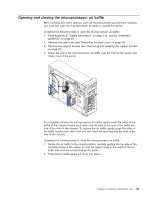
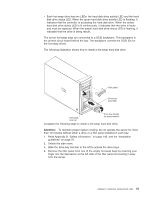
The following notes describe the types of drives that the server supports and other information that you must consider when installing a hard disk drive: v Make sure that you have all the cables and other equipment that is specified in the documentation that comes with the drive. v Check the instructions that come with the drive to see whether you must set any switches or jumpers on the drive. If you are installing a SCSI device, be sure to set the SCSI ID for that device. v Diskette drives, tape drives, CD-ROM, CD-RW, and DVD drives are examples of removable-media drives. You can install removable-media drives in bays 1, 2, and 3 only. v The integrated IDE controller in the server supports up to two IDE devices. v You can install a 3.5-in. slim-high or 5.25-in. half-high removable-media drive, such as a tape backup drive, CD-RW drive, or DVD drive, in bay 2. v The server supports only one diskette drive. v To install a 3.5-in. drive in a 5.25-in. bay, you must use the 5.25-in. conversion kit. Contact IBM to order the conversion kit. v The electromagnetic interference (EMI) integrity and cooling of the server are protected by having all bays and PCI slots covered or occupied. When you install a drive or PCI adapter, save the EMC shield and filler panel from the bay or the PCI adapter slot cover in the event you later remove the option. v For a complete list of supported options for the server, go to http://www.ibm.com/pc/support/. Installing a drive in bay 2 Complete the following steps to install a drive in bay 2: 1. Read Appendix B, "Safety information," on page 143, and the "Installation guidelines" on page 25. 2. Turn off the server and peripheral devices, and disconnect the power cords and all external cables. 3. Remove the side cover (see "Removing the side cover" on page 28). 4. Remove the support bracket (see "Removing and installing the support bracket" on page 32). 5. Remove the bezel (see "Removing the bezel" on page 30). 6. Use a screwdriver to pry the filler panel and EMC shield away from the server. Note: If you are installing a drive that contains a laser, observe the following safety precaution. 38 xSeries 226 Type 8488 and 8648: Hardware Maintenance Manual and Troubleshooting Guide
-
 1
1 -
2
-
3
-
4
-
5
-
6
-
7
-
8
-
9
-
10
-
11
-
12
-
13
-
14
-
15
-
16
-
17
-
18
-
19
-
20
-
21
-
22
-
23
-
24
-
25
-
26
-
27
-
28
-
29
-
30
-
31
-
32
-
33
-
34
-
35
-
36
-
37
-
38
-
39
-
40
-
41
-
42
-
 43
43 -
 44
44 -
 45
45 -
 46
46 -
 47
47 -
 48
48 -
 49
49 -
 50
50 -
 51
51 -
 52
52 -
 53
53 -
54
-
55
-
56
-
57
-
58
-
59
-
60
-
61
-
62
-
63
-
64
-
65
-
66
-
67
-
68
-
69
-
70
-
71
-
72
-
73
-
74
-
75
-
76
-
77
-
78
-
79
-
80
-
81
-
82
-
83
-
84
-
85
-
86
-
87
-
88
-
89
-
90
-
91
-
92
-
93
-
94
-
95
-
96
-
97
-
98
-
99
-
100
-
101
-
102
-
103
-
104
-
105
-
106
-
107
-
108
-
109
-
110
-
111
-
112
-
113
-
114
-
115
-
116
-
117
-
118
-
119
-
120
-
121
-
122
-
123
-
124
-
125
-
126
-
127
-
128
-
129
-
130
-
131
-
132
-
133
-
134
-
135
-
136
-
137
-
138
-
139
-
140
-
141
-
142
-
143
-
144
-
145
-
146
-
147
-
148
-
149
-
150
-
151
-
152
-
153
-
154
-
155
-
156
-
157
-
158
-
159
-
160
-
161
-
162
-
163
-
164
-
165
-
166
-
167
-
168
-
169
-
170
-
171
-
172
-
173
-
174
-
175
-
176
-
177
-
178
-
179
-
180
-
181
-
182
-
183
-
184
-
185
-
186
-
187
-
188
-
189
-
190
-
191
-
192
-
193
-
194
-
195
-
196
-
197
-
198
-
199
-
200
 |
 |