IBM 8488 Hardware Maintenance Manual - Page 73
Input/output, connectors
 |
UPC - 000435695277
View all IBM 8488 manuals
Add to My Manuals
Save this manual to your list of manuals |
Page 73 highlights
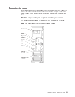
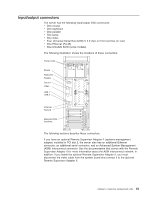
Input/output connectors The server has the following input/output (I/O) connectors: v One mouse v One keyboard v One parallel v Two serial v One video v Four Universal Serial Bus (USB) V 2.0 (two on front and two on rear) v One Ethernet (RJ-45) v One Ultra320 SCSI (some models) The following illustration shows the locations of these connectors. Power cords Mouse Keyboard Parallel Serial 1 Video USB 1 USB 2 Ethernet Serial 2 External SCSI knockout The following sections describe these connectors. If you have an optional Remote Supervisor Adapter II (systems-management adapter) installed in PCI slot 2, the server also has an additional Ethernet connector, an additional serial connector, and an Advanced System Management (ASM) Interconnect connector. See the documentation that comes with the Remote Supervisor Adapter II for more information about the ASM Interconnect network. In addition, if you install the optional Remote Supervisor Adapter II, you must disconnect the video cable from the system board and connect it to the optional Remote Supervisor Adapter II. Chapter 4. Customer replacement units 63
-
 1
1 -
2
-
3
-
4
-
5
-
6
-
7
-
8
-
9
-
10
-
11
-
12
-
13
-
14
-
15
-
16
-
17
-
18
-
19
-
20
-
21
-
22
-
23
-
24
-
25
-
26
-
27
-
28
-
29
-
30
-
31
-
32
-
33
-
34
-
35
-
36
-
37
-
38
-
39
-
40
-
41
-
42
-
43
-
44
-
45
-
46
-
47
-
48
-
49
-
50
-
51
-
52
-
53
-
54
-
55
-
56
-
57
-
58
-
59
-
60
-
61
-
62
-
63
-
64
-
65
-
66
-
67
-
 68
68 -
 69
69 -
 70
70 -
 71
71 -
 72
72 -
 73
73 -
 74
74 -
 75
75 -
 76
76 -
 77
77 -
 78
78 -
79
-
80
-
81
-
82
-
83
-
84
-
85
-
86
-
87
-
88
-
89
-
90
-
91
-
92
-
93
-
94
-
95
-
96
-
97
-
98
-
99
-
100
-
101
-
102
-
103
-
104
-
105
-
106
-
107
-
108
-
109
-
110
-
111
-
112
-
113
-
114
-
115
-
116
-
117
-
118
-
119
-
120
-
121
-
122
-
123
-
124
-
125
-
126
-
127
-
128
-
129
-
130
-
131
-
132
-
133
-
134
-
135
-
136
-
137
-
138
-
139
-
140
-
141
-
142
-
143
-
144
-
145
-
146
-
147
-
148
-
149
-
150
-
151
-
152
-
153
-
154
-
155
-
156
-
157
-
158
-
159
-
160
-
161
-
162
-
163
-
164
-
165
-
166
-
167
-
168
-
169
-
170
-
171
-
172
-
173
-
174
-
175
-
176
-
177
-
178
-
179
-
180
-
181
-
182
-
183
-
184
-
185
-
186
-
187
-
188
-
189
-
190
-
191
-
192
-
193
-
194
-
195
-
196
-
197
-
198
-
199
-
200
 |
 |
