IBM 8488 Hardware Maintenance Manual - Page 78
Microprocessor
 |
UPC - 000435695277
View all IBM 8488 manuals
Add to My Manuals
Save this manual to your list of manuals |
Page 78 highlights
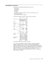
Microprocessor and heat sink Before you begin: v Read the "Installation guidelines" on page 25. v Read Appendix B, "Safety information," on page 143. v Review the information in "System reliability guidelines" on page 25. To remove the microprocessor and heat sink, complete the following steps. DIMMs Heat-sink release levers Microprocessor 2 Heat sink 2 VRM Microprocessor baffle assembly Microprocessor air baffle 1. Turn off the server and remove external cables. 2. Remove the side cover (see "Removing the side cover" on page 28). 3. Remove the frame-support bracket (see "Removing and installing the support bracket" on page 32). 4. Disconnect any cables that impede access to the microprocessor. 5. Remove the heat sink from the microprocessor: a. Press the microprocessor-baffle release lever down, move it toward the other microprocessor, and lift it up to the open position. b. Slide the heat-sink assembly toward the front of the server and tip the rear flange out of the heat-sink socket. c. Lift the heat sink up and out of the server. Note: It might be necessary to gently twist the heat sink to loosen it from the microprocessor. Important: Be careful when handling the microprocessor and heat sink. If the thermal grease between the microprocessor and heat sink will be reused, do not contaminate it. If replacement thermal grease is provided with the replacement part, be sure to remove all traces of existing thermal grease from the remaining part before applying the new thermal grease. 68 xSeries 226 Type 8488 and 8648: Hardware Maintenance Manual and Troubleshooting Guide
-
 1
1 -
2
-
3
-
4
-
5
-
6
-
7
-
8
-
9
-
10
-
11
-
12
-
13
-
14
-
15
-
16
-
17
-
18
-
19
-
20
-
21
-
22
-
23
-
24
-
25
-
26
-
27
-
28
-
29
-
30
-
31
-
32
-
33
-
34
-
35
-
36
-
37
-
38
-
39
-
40
-
41
-
42
-
43
-
44
-
45
-
46
-
47
-
48
-
49
-
50
-
51
-
52
-
53
-
54
-
55
-
56
-
57
-
58
-
59
-
60
-
61
-
62
-
63
-
64
-
65
-
66
-
67
-
68
-
69
-
70
-
71
-
72
-
 73
73 -
 74
74 -
 75
75 -
 76
76 -
 77
77 -
 78
78 -
 79
79 -
 80
80 -
 81
81 -
 82
82 -
 83
83 -
84
-
85
-
86
-
87
-
88
-
89
-
90
-
91
-
92
-
93
-
94
-
95
-
96
-
97
-
98
-
99
-
100
-
101
-
102
-
103
-
104
-
105
-
106
-
107
-
108
-
109
-
110
-
111
-
112
-
113
-
114
-
115
-
116
-
117
-
118
-
119
-
120
-
121
-
122
-
123
-
124
-
125
-
126
-
127
-
128
-
129
-
130
-
131
-
132
-
133
-
134
-
135
-
136
-
137
-
138
-
139
-
140
-
141
-
142
-
143
-
144
-
145
-
146
-
147
-
148
-
149
-
150
-
151
-
152
-
153
-
154
-
155
-
156
-
157
-
158
-
159
-
160
-
161
-
162
-
163
-
164
-
165
-
166
-
167
-
168
-
169
-
170
-
171
-
172
-
173
-
174
-
175
-
176
-
177
-
178
-
179
-
180
-
181
-
182
-
183
-
184
-
185
-
186
-
187
-
188
-
189
-
190
-
191
-
192
-
193
-
194
-
195
-
196
-
197
-
198
-
199
-
200
 |
 |
