IBM 8488 Hardware Maintenance Manual - Page 65
ServeRAID-7t
 |
UPC - 000435695277
View all IBM 8488 manuals
Add to My Manuals
Save this manual to your list of manuals |
Page 65 highlights
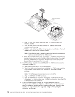
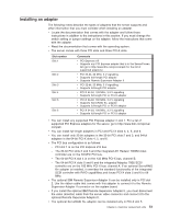
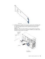
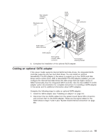
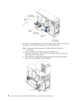
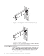
Rear adapterretaining bracket Expansion-slot cover SCSI signal cable SCSI LED connector SCSI signal cable connector SCSI adapter SCSI activity indicator cable connector Front adapterretaining bracket 4. Complete the installation of the optional SCSI adapter. Cabling an optional SATA adapter If the server model supports internal SATA hard disk drives, the integrated SATA controller supports only two hard disk drives. You can install an optional ServeRAID-7t S-ATA adapter in the server to support up to four SATA hard disk drives and to control them. With a ServeRAID-7t S-ATA adapter installed, you can configure the internal hard disk drives into disk arrays that use higher levels of RAID functionality than the integrated SATA controller. See the ServeRAID-7t S-ATA adapter option documentation for complete instructions for installing a SATA adapter in the server and for additional information about SATA adapters. Complete the following steps to cable an optional SATA adapter: 1. Install the SATA adapter (see "Installing an adapter" on page 51). 2. Disconnect the two SATA cables from the system board Serial ATA connectors and connect them to the SATA adapter. These are the signal cables for the SATA drives in bays 7 and 6 (see "System board internal connectors" on page 86). Chapter 4. Customer replacement units 55
-
 1
1 -
2
-
3
-
4
-
5
-
6
-
7
-
8
-
9
-
10
-
11
-
12
-
13
-
14
-
15
-
16
-
17
-
18
-
19
-
20
-
21
-
22
-
23
-
24
-
25
-
26
-
27
-
28
-
29
-
30
-
31
-
32
-
33
-
34
-
35
-
36
-
37
-
38
-
39
-
40
-
41
-
42
-
43
-
44
-
45
-
46
-
47
-
48
-
49
-
50
-
51
-
52
-
53
-
54
-
55
-
56
-
57
-
58
-
59
-
 60
60 -
 61
61 -
 62
62 -
 63
63 -
 64
64 -
 65
65 -
 66
66 -
 67
67 -
 68
68 -
 69
69 -
 70
70 -
71
-
72
-
73
-
74
-
75
-
76
-
77
-
78
-
79
-
80
-
81
-
82
-
83
-
84
-
85
-
86
-
87
-
88
-
89
-
90
-
91
-
92
-
93
-
94
-
95
-
96
-
97
-
98
-
99
-
100
-
101
-
102
-
103
-
104
-
105
-
106
-
107
-
108
-
109
-
110
-
111
-
112
-
113
-
114
-
115
-
116
-
117
-
118
-
119
-
120
-
121
-
122
-
123
-
124
-
125
-
126
-
127
-
128
-
129
-
130
-
131
-
132
-
133
-
134
-
135
-
136
-
137
-
138
-
139
-
140
-
141
-
142
-
143
-
144
-
145
-
146
-
147
-
148
-
149
-
150
-
151
-
152
-
153
-
154
-
155
-
156
-
157
-
158
-
159
-
160
-
161
-
162
-
163
-
164
-
165
-
166
-
167
-
168
-
169
-
170
-
171
-
172
-
173
-
174
-
175
-
176
-
177
-
178
-
179
-
180
-
181
-
182
-
183
-
184
-
185
-
186
-
187
-
188
-
189
-
190
-
191
-
192
-
193
-
194
-
195
-
196
-
197
-
198
-
199
-
200
 |
 |
