IBM QS21 User Guide - Page 18
BladeCenter - cell b e
 |
UPC - 883436016940
View all IBM QS21 manuals
Add to My Manuals
Save this manual to your list of manuals |
Page 18 highlights
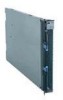
The BladeCenter QS21 conforms to the generic BladeCenter infrastructure and is designed for operation with the high-speed interconnect in the following BladeCenter units: v BladeCenter H Type 8852 v BladeCenter HT Types 8740 and 8750 (enterprise environment only) v BladeCenter S Types 7779 and 8886 (non RAID type only) BladeCenter QS21 support is only available for the BladeCenter units listed above. Figure 1. BladeCenter QS21 The BladeCenter QS21 has the following major components: v 2 Cell/B.E. processor chips (Cell/B.E.-0 and Cell/B.E.-1) operating at 3.2 GHz v 2 GB XDR system memory with ECC, 1 GB per Cell/B.E. chip v 2 Cell/B.E. companion chips, one per Cell/B.E. chip v 2 x 16 lanes PCIe, 2 masters per Cell/B.E. companion chip v 1 PCI-X bus per Cell/B.E. companion chip, running at 100 MHz v Interface to optional DDR2 memory, for use as the I/O Buffer v Onboard Dual Channel Gb-Ethernet controller BCM5704S v Onboard USB controller NEC uPD720101 v 1 BladeCenter PCI-X expansion card connector v 1 BladeCenter High-Speed connector for 2 x 8 PCIe buses v 1 Special additional I/O expansion connector for 2 x 16 PCIe buses v 4 DIMM slots (2 slots per Cell/B.E. companion chip) for optional I/O Buffer DDR2 VLP DIMMs v Integrated Renesas 2166 Service processor (BMC, IPMI compliant code stack) The average maximum for power budgeting is 300 W for a QS21 blade server without options. 2 QS21 Installation and User's Guide
-
 1
1 -
2
-
3
-
4
-
5
-
6
-
7
-
8
-
9
-
10
-
11
-
12
-
 13
13 -
 14
14 -
 15
15 -
 16
16 -
 17
17 -
 18
18 -
 19
19 -
 20
20 -
 21
21 -
 22
22 -
 23
23 -
24
-
25
-
26
-
27
-
28
-
29
-
30
-
31
-
32
-
33
-
34
-
35
-
36
-
37
-
38
-
39
-
40
-
41
-
42
-
43
-
44
-
45
-
46
-
47
-
48
-
49
-
50
-
51
-
52
-
53
-
54
-
55
-
56
-
57
-
58
-
59
-
60
-
61
-
62
-
63
-
64
-
65
-
66
-
67
-
68
-
69
-
70
-
71
-
72
-
73
-
74
-
75
-
76
-
77
-
78
-
79
-
80
-
81
-
82
-
83
-
84
-
85
-
86
-
87
-
88
-
89
-
90
-
91
-
92
-
93
-
94
-
95
-
96
-
97
-
98
-
99
-
100
-
101
-
102
-
103
-
104
-
105
-
106
-
107
-
108
-
109
-
110
 |
 |
