Icom M803 Instruction Manual - Page 76
CONNECTIONS AND INSTALLATION, Supplied accessories, Connections, Connecting the microphone
 |
View all Icom M803 manuals
Add to My Manuals
Save this manual to your list of manuals |
Page 76 highlights
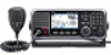
9 CONNECTIONS AND INSTALLATION ■ Supplied accessories Microphone Remote control cable (5.1 m, 16.7 ft) DC power cable GPS antenna and double-sided adhesive pad Microphone hanger and Spare fuse screws (3 × 16 mm) (ATC 30A) Spare fuse (BFLP 5A) Mounting bracket kit for the remote controller Tuner connector kit Accessory connector (8-pin DIN) Mounting bracket Flat washers (M5) Screws (M5) Self-tapping screws (M5) Spring washers (M5) Mounting bracket kit for the main unit Mounting bracket Flat washers (M5) Knobs Self-tapping screws (M5) Spring washers (M5) NOTE: Some accessories are not supplied, or the shape is different, depending on the transceiver version. ■ Connections D Connecting the microphone 1. Insert the microphone's connector into the microphone jack on the remote controller's front panel. 2. Rotate the connector clockwise until it is completely tightened. CAUTION: • Be sure that the microphone's connector is screwed in completely. Otherwise, the remote controller may lose its waterproof protection. • DO NOT use non-Icom microphones. Other manufacturer's microphones have different pin assignments, and connection to the remote controller may damage it. Microphone's connector 68
-
 1
1 -
2
-
3
-
4
-
5
-
6
-
7
-
8
-
9
-
10
-
11
-
12
-
13
-
14
-
15
-
16
-
17
-
18
-
19
-
20
-
21
-
22
-
23
-
24
-
25
-
26
-
27
-
28
-
29
-
30
-
31
-
32
-
33
-
34
-
35
-
36
-
37
-
38
-
39
-
40
-
41
-
42
-
43
-
44
-
45
-
46
-
47
-
48
-
49
-
50
-
51
-
52
-
53
-
54
-
55
-
56
-
57
-
58
-
59
-
60
-
61
-
62
-
63
-
64
-
65
-
66
-
67
-
68
-
69
-
70
-
 71
71 -
 72
72 -
 73
73 -
 74
74 -
 75
75 -
 76
76 -
 77
77 -
 78
78 -
 79
79 -
 80
80 -
 81
81 -
82
-
83
-
84
-
85
-
86
-
87
-
88
-
89
-
90
-
91
-
92
-
93
-
94
-
95
-
96
 |
 |
