Intel D5400XS Product Guide - Page 39
Installing and Removing Memory, Installing DIMMs - with quad channel
 |
UPC - 735858198684
View all Intel D5400XS manuals
Add to My Manuals
Save this manual to your list of manuals |
Page 39 highlights
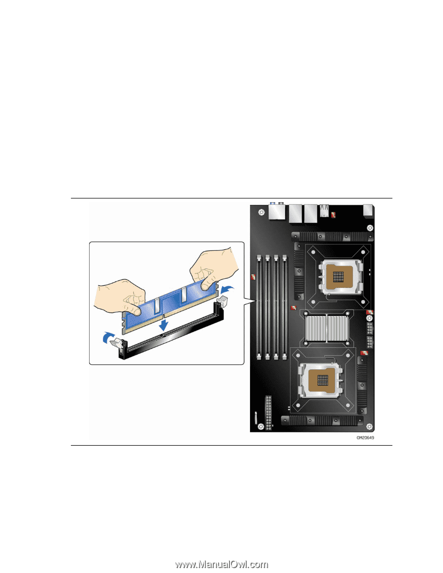
Installing and Replacing Desktop Board Components Installing and Removing Memory Desktop board D5400XS has four 240-pin FBDIMM sockets providing quad-channel memory support with one DIMM per channel. The sockets are keyed so that they will accept only FBDIMMs. Installing DIMMs To install a DIMM, follow these steps: 1. Observe the precautions in "Before You Begin" on page 29. 2. Turn off all peripheral devices connected to the computer. Turn off the computer and disconnect the AC power cord. 3. Remove the computer's cover and locate the DIMM sockets (see Figure 17). Figure 17. Installing a DIMM 4. Make sure the clips at either end of the DIMM socket(s) are pushed outward to the open position. 5. Holding the DIMM by the edges, remove it from its anti-static package. 39
-
 1
1 -
2
-
3
-
4
-
5
-
6
-
7
-
8
-
9
-
10
-
11
-
12
-
13
-
14
-
15
-
16
-
17
-
18
-
19
-
20
-
21
-
22
-
23
-
24
-
25
-
26
-
27
-
28
-
29
-
30
-
31
-
32
-
33
-
 34
34 -
 35
35 -
 36
36 -
 37
37 -
 38
38 -
 39
39 -
 40
40 -
 41
41 -
 42
42 -
 43
43 -
 44
44 -
45
-
46
-
47
-
48
-
49
-
50
-
51
-
52
-
53
-
54
-
55
-
56
-
57
-
58
-
59
-
60
-
61
-
62
-
63
-
64
-
65
-
66
-
67
-
68
-
69
-
70
-
71
-
72
-
73
-
74
-
75
-
76
-
77
-
78
-
79
-
80
-
81
-
82
-
83
-
84
-
85
-
86
-
87
-
88
-
89
-
90
 |
 |