Intel D5400XS Product Guide - Page 50
USB 2.0 Headers, Consumer IR (CIR) Headers, Table 9. USB 2.0 Header Signal Names
 |
UPC - 735858198684
View all Intel D5400XS manuals
Add to My Manuals
Save this manual to your list of manuals |
Page 50 highlights
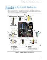
Intel Desktop Board D5400XS Product Guide USB 2.0 Headers Figure 23, F shows the location of the USB 2.0 headers. Table 9 shows the pin assignments and signal names for each USB 2.0 header. Each USB header can be used to connect two USB devices. Table 9. USB 2.0 Header Signal Names USB Port A Pin Signal Name Pin 1 Power (+5 V) 2 3 D- 4 5 D+ 6 7 Ground 8 9 Key 10 Note: USB ports may be assigned as needed. USB Port B Signal Name Power (+5 V) DD+ Ground No Connection NOTE Computer systems that have an unshielded cable attached to a USB port might not meet FCC Class B requirements, even if no device or a low-speed USB device is attached to the cable. Use a shielded cable that meets the requirements for a full-speed USB device. Consumer IR (CIR) Headers The Desktop Board has two CIR headers: the input or receiver header (Figure 23, G) and the output or emitter header (Figure 23, H). The receiver header consists of a filtered translated infrared input compliant with Microsoft CIR specifications and a "learning" infrared input. The learning input is a high-pass input which the computer can use to "learn" to speak the infrared communication language of other user remotes. The emitter header consists of two output ports which the computer can use to emulate "learned" infrared commands in order to control external electronic hardware. NOTE The Consumer IR option must be enabled in the system BIOS before it can function. Press at boot to enter the system BIOS, and go to Advanced > Peripheral Configuration > Enhanced Consumer IR, and set this option to Enabled. Table 10 shows the pin assignments and signal names for the front panel CIR receiver (input) header and Table 11 shows the pin assignments and signal names for the back panel CIR emitter (output) header. 50
-
 1
1 -
2
-
3
-
4
-
5
-
6
-
7
-
8
-
9
-
10
-
11
-
12
-
13
-
14
-
15
-
16
-
17
-
18
-
19
-
20
-
21
-
22
-
23
-
24
-
25
-
26
-
27
-
28
-
29
-
30
-
31
-
32
-
33
-
34
-
35
-
36
-
37
-
38
-
39
-
40
-
41
-
42
-
43
-
44
-
 45
45 -
 46
46 -
 47
47 -
 48
48 -
 49
49 -
 50
50 -
 51
51 -
 52
52 -
 53
53 -
 54
54 -
 55
55 -
56
-
57
-
58
-
59
-
60
-
61
-
62
-
63
-
64
-
65
-
66
-
67
-
68
-
69
-
70
-
71
-
72
-
73
-
74
-
75
-
76
-
77
-
78
-
79
-
80
-
81
-
82
-
83
-
84
-
85
-
86
-
87
-
88
-
89
-
90
 |
 |