Intel D5400XS Product Guide - Page 47
Connecting to the Internal Headers and Connectors, Internal Headers and Connectors
 |
UPC - 735858198684
View all Intel D5400XS manuals
Add to My Manuals
Save this manual to your list of manuals |
Page 47 highlights
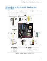
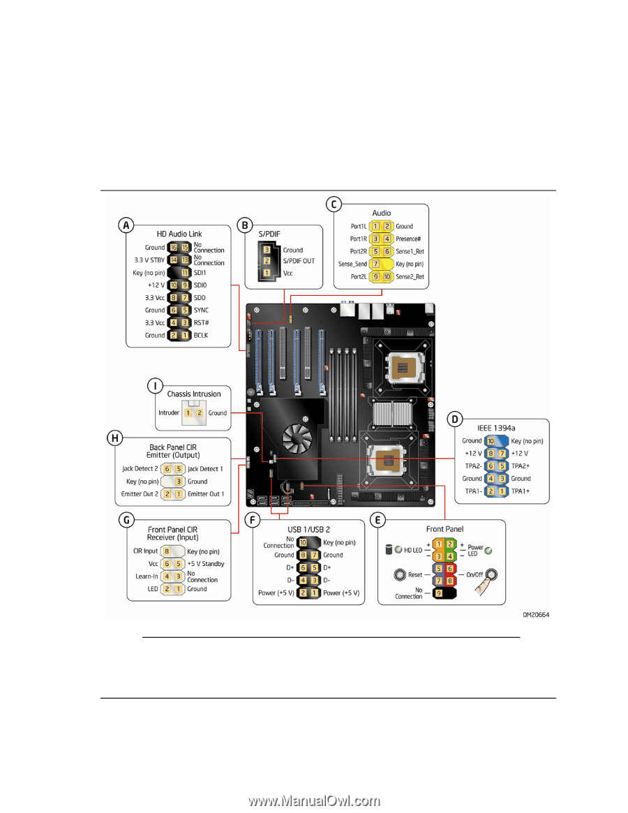
Installing and Replacing Desktop Board Components Connecting to the Internal Headers and Connectors Before connecting cables to any of the internal headers, observe the precautions in "Before You Begin" on page 29. Figure 23 shows the location of the internal headers and connectors on Intel Desktop Board D5400XS. Item Description A HD Audio Link B S/PDIF C Front panel audio D IEEE 1394a E Front panel Item Description F USB 2.0 (2) G Front panel CIR receiver (input) H Back panel CIR emitter (output) I Chassis intrusion Figure 23. Internal Headers and Connectors 47
-
 1
1 -
2
-
3
-
4
-
5
-
6
-
7
-
8
-
9
-
10
-
11
-
12
-
13
-
14
-
15
-
16
-
17
-
18
-
19
-
20
-
21
-
22
-
23
-
24
-
25
-
26
-
27
-
28
-
29
-
30
-
31
-
32
-
33
-
34
-
35
-
36
-
37
-
38
-
39
-
40
-
41
-
 42
42 -
 43
43 -
 44
44 -
 45
45 -
 46
46 -
 47
47 -
 48
48 -
 49
49 -
 50
50 -
 51
51 -
 52
52 -
53
-
54
-
55
-
56
-
57
-
58
-
59
-
60
-
61
-
62
-
63
-
64
-
65
-
66
-
67
-
68
-
69
-
70
-
71
-
72
-
73
-
74
-
75
-
76
-
77
-
78
-
79
-
80
-
81
-
82
-
83
-
84
-
85
-
86
-
87
-
88
-
89
-
90
 |
 |
Installing and Replacing Desktop Board Components
47
Connecting to the Internal Headers and
Connectors
Before connecting cables to any of the internal headers, observe the precautions in
“Before You Begin” on page 29.
Figure 23 shows the location of the internal headers
and connectors on Intel Desktop Board D5400XS.
Item
Description
Item
Description
A
HD Audio Link
F
USB 2.0 (2)
B
S/PDIF
G
Front panel CIR receiver (input)
C
Front panel audio
H
Back panel CIR emitter (output)
D
IEEE 1394a
I
Chassis intrusion
E
Front panel
Figure 23.
Internal Headers and Connectors