Intel D5400XS Product Guide - Page 7

Remove the Processor from the Protective Processor Cover - bios

Page 7 highlights

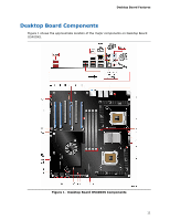
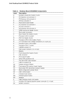
Contents A Error Messages and Indicators BIOS Beep Codes 71 BIOS Error Messages 71 Port 80h POST Codes 72 B Regulatory Compliance Safety Standards 77 Place Battery Marking 77 European Union Declaration of Conformity Statement 78 Product Ecology Statements 79 Recycling Considerations 79 Lead-free 2LI/Pb-free 2LI Board 82 Restriction of Hazardous Substances (RoHS 83 EU RoHS 83 China RoHS 84 EMC Regulations 86 Ensure Electromagnetic Compatibility (EMC) Compliance 87 Product Certifications 88 Board-Level Certification Markings 88 Chassis and Component Certifications 89 Figures 1. Desktop Board D5400XS Components 11 2. LAN Status LEDs 15 3. Disk Drive Access Indicator 18 4. Location of the Standby Power Indicator 24 5. Onboard Power and Reset Buttons 26 6. Location of the VR and CPU LEDs 27 7. Installing the I/O Shield 31 8. Desktop Board D5400XS Mounting Screw Hole Locations 32 9. Lift the Socket Lever 33 10. Lift the Load Plate 34 11. Remove the Protective Socket Cover 34 12. Remove the Processor from the Protective Processor Cover 35 13. Install the Processor 35 14. Close the Load Plate 36 15. Processor Fan Heat Sink Headers 37 16. Installing a Typical MCH Heat Sink Fan 38 17. Installing a DIMM 39 18. DIMM Cooling Fan Header 41 19. Installing a PCI Express x16 Card 42 20. Removing a PCI Express x16 Card 43 21. Connecting the IDE Cable 45 22. Connecting Serial ATA Cables 46 23. Internal Headers and Connectors 47 24. Back Panel Audio Connectors 52 25. Location of the Chassis Fan Headers 53 26. Connecting Power Supply Cables 54 27. Location of the BIOS Configuration Jumper Block 55 vii

  • 1
  • 2
  • 3
  • 4
  • 5
  • 6
  • 7
  • 8
  • 9
  • 10
  • 11
  • 12
  • 13
  • 14
  • 15
  • 16
  • 17
  • 18
  • 19
  • 20
  • 21
  • 22
  • 23
  • 24
  • 25
  • 26
  • 27
  • 28
  • 29
  • 30
  • 31
  • 32
  • 33
  • 34
  • 35
  • 36
  • 37
  • 38
  • 39
  • 40
  • 41
  • 42
  • 43
  • 44
  • 45
  • 46
  • 47
  • 48
  • 49
  • 50
  • 51
  • 52
  • 53
  • 54
  • 55
  • 56
  • 57
  • 58
  • 59
  • 60
  • 61
  • 62
  • 63
  • 64
  • 65
  • 66
  • 67
  • 68
  • 69
  • 70
  • 71
  • 72
  • 73
  • 74
  • 75
  • 76
  • 77
  • 78
  • 79
  • 80
  • 81
  • 82
  • 83
  • 84
  • 85
  • 86
  • 87
  • 88
  • 89
  • 90

Contents
vii
A
Error Messages and Indicators
BIOS Beep Codes
...............................................................................................
71
BIOS Error Messages
..........................................................................................
71
Port 80h POST Codes
..........................................................................................
72
B
Regulatory Compliance
Safety Standards
...............................................................................................
77
Place Battery Marking
.................................................................................
77
European Union Declaration of Conformity Statement
..............................................
78
Product Ecology Statements
................................................................................
79
Recycling Considerations
.............................................................................
79
Lead-free 2LI/Pb-free 2LI Board
...................................................................
82
Restriction of Hazardous Substances (RoHS)
..................................................
83
EU RoHS
............................................................................................
83
China RoHS
........................................................................................
84
EMC Regulations
................................................................................................
86
Ensure Electromagnetic Compatibility (EMC) Compliance
..................................
87
Product Certifications
..........................................................................................
88
Board-Level Certification Markings
................................................................
88
Chassis and Component Certifications
............................................................
89
Figures
1. Desktop Board D5400XS Components
.............................................................
11
2. LAN Status LEDs
..........................................................................................
15
3. Disk Drive Access Indicator
............................................................................
18
4.
Location of the Standby Power Indicator
..........................................................
24
5. Onboard Power and Reset Buttons
..................................................................
26
6.
Location of the VR and CPU LEDs
....................................................................
27
7. Installing the I/O Shield
................................................................................
31
8.
Desktop Board D5400XS Mounting Screw Hole Locations
....................................
32
9. Lift the Socket Lever
.....................................................................................
33
10. Lift the Load Plate
.........................................................................................
34
11. Remove the Protective Socket Cover
...............................................................
34
12. Remove the Processor from the Protective Processor Cover
................................
35
13. Install the Processor
.....................................................................................
35
14. Close the Load Plate
.....................................................................................
36
15. Processor Fan Heat Sink Headers
....................................................................
37
16. Installing a Typical MCH Heat Sink Fan
............................................................
38
17. Installing a DIMM
.........................................................................................
39
18. DIMM Cooling Fan Header
..............................................................................
41
19. Installing a PCI Express x16 Card
...................................................................
42
20. Removing a PCI Express x16 Card
..................................................................
43
21. Connecting the IDE Cable
..............................................................................
45
22. Connecting Serial ATA Cables
.........................................................................
46
23. Internal Headers and Connectors
....................................................................
47
24. Back Panel Audio Connectors
.........................................................................
52
25. Location of the Chassis Fan Headers
................................................................
53
26. Connecting Power Supply Cables
....................................................................
54
27. Location of the BIOS Configuration Jumper Block
..............................................
55