Intel D865GRH D865GRH_TechProdSpec. - Page 44
Audio Connectors
 |
View all Intel D865GRH manuals
Add to My Manuals
Save this manual to your list of manuals |
Page 44 highlights
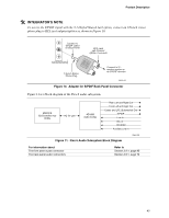
Intel Desktop Board D865GRH Technical Product Specification 1.9.3 Audio Connectors 1.9.3.1 Front Panel Audio Connector A 2 x 5-pin connector provides mic in and line out signals for front panel audio connectors. For information about The location of the connector The signal names of the front panel audio connector Refer to Figure 17, page 74 Table 26, page 75 ✏ NOTE The front panel audio connector is alternately used as a jumper block for routing audio signals. Refer to Section 2.9.1 on page 85 for more information. 1.9.3.2 Auxiliary Line In Connector A 1 x 4-pin ATAPI-style connector connects the left and right channel signals of an internal audio device to the audio subsystem. For information about The location of the auxiliary line in connector The signal names of the auxiliary line in connector Refer to Figure 17, page 74 Table 24, page 75 1.9.3.3 ATAPI CD-ROM Audio Connector A 1 x 4-pin ATAPI-style connector connects an internal ATAPI CD-ROM drive to the audio mixer. For information about The location of the ATAPI CD-ROM connector The signal names of the ATAPI CD-ROM connector Refer to Figure 17, page 74 Table 25, page 75 44
-
 1
1 -
2
-
3
-
4
-
5
-
6
-
7
-
8
-
9
-
10
-
11
-
12
-
13
-
14
-
15
-
16
-
17
-
18
-
19
-
20
-
21
-
22
-
23
-
24
-
25
-
26
-
27
-
28
-
29
-
30
-
31
-
32
-
33
-
34
-
35
-
36
-
37
-
38
-
 39
39 -
 40
40 -
 41
41 -
 42
42 -
 43
43 -
 44
44 -
 45
45 -
 46
46 -
 47
47 -
 48
48 -
 49
49 -
50
-
51
-
52
-
53
-
54
-
55
-
56
-
57
-
58
-
59
-
60
-
61
-
62
-
63
-
64
-
65
-
66
-
67
-
68
-
69
-
70
-
71
-
72
-
73
-
74
-
75
-
76
-
77
-
78
-
79
-
80
-
81
-
82
-
83
-
84
-
85
-
86
-
87
-
88
-
89
-
90
-
91
-
92
-
93
-
94
-
95
-
96
-
97
-
98
-
99
-
100
-
101
-
102
-
103
-
104
-
105
-
106
-
107
-
108
-
109
-
110
-
111
-
112
-
113
-
114
-
115
-
116
-
117
-
118
-
119
-
120
-
121
-
122
-
123
-
124
-
125
-
126
-
127
-
128
-
129
-
130
-
131
-
132
-
133
-
134
-
135
-
136
-
137
-
138
-
139
-
140
-
141
-
142
 |
 |