Intel D865GRH D865GRH_TechProdSpec. - Page 8

s, Tables - 865g

Page 8 highlights

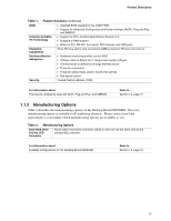
Intel Desktop Board D865GRH Technical Product Specification Figures 1. Desktop Board D865GRH Components 14 2. Block Diagram ...15 3. Memory Channel Configuration 23 4. Examples of Dual Channel Configuration with Dynamic Mode 24 5. Example of Dual Channel Configuration without Dynamic Mode 25 6. Examples of Single Channel Configuration with Dynamic Mode 26 7. Examples of Single Channel Configuration without Dynamic Mode 27 8. Intel 865G Chipset Block Diagram 28 9. Back Panel Audio Connector Options for Flex 6 Audio Subsystem 42 10. Adapter for S/PDIF Back Panel Connector 43 11. Flex 6 Audio Subsystem Block Diagram 43 12. LAN Connector LED Locations 45 13. Thermal Monitoring...47 14. Location of the Standby Power Indicator LED 54 15. Detailed System Memory Address Map 64 16. Back Panel Connectors 72 17. Audio Connectors ...74 18. Power and Hardware Control Connectors 76 19. D865GRH Add-in Board and Peripheral Interface Connectors 79 20. External I/O Connectors 81 21. Connection Diagram for Front Panel Connector 82 22. Connection Diagram for Front Panel USB Connectors 84 23. Location of the Jumper Blocks 85 24. Desktop Board D865GRH Dimensions 87 25. I/O Shield Dimensions 88 26. Localized High Temperature Zones 91 Tables 1. Feature Summary...12 2. Manufacturing Options 13 3. Specifications ...17 4. Supported System Bus Frequency and Memory Speed Combinations 21 5. Supported Memory Configurations 22 6. Characteristics of Dual/Single Channel Configuration with/without Dynamic Mode.....23 7. Direct Draw Supported Modes 30 8. Video BIOS Video Modes Supported for Analog CRTs 31 9. Supported Modes for DDR400/DDR333 Dual Channel Configuration 32 10. Supported Modes for DDR266 Dual Channel and DDR333/DDR400 Single Channel Configurations 33 11. Supported Modes for DDR266 Single Channel Configuration 34 12. LAN Connector LED States 45 13. Effects of Pressing the Power Switch 49 14. Power States and Targeted System Power 49 15. Wake-up Devices and Events 50 16. Fan Connector Function/Operation 52 viii

  • 1
  • 2
  • 3
  • 4
  • 5
  • 6
  • 7
  • 8
  • 9
  • 10
  • 11
  • 12
  • 13
  • 14
  • 15
  • 16
  • 17
  • 18
  • 19
  • 20
  • 21
  • 22
  • 23
  • 24
  • 25
  • 26
  • 27
  • 28
  • 29
  • 30
  • 31
  • 32
  • 33
  • 34
  • 35
  • 36
  • 37
  • 38
  • 39
  • 40
  • 41
  • 42
  • 43
  • 44
  • 45
  • 46
  • 47
  • 48
  • 49
  • 50
  • 51
  • 52
  • 53
  • 54
  • 55
  • 56
  • 57
  • 58
  • 59
  • 60
  • 61
  • 62
  • 63
  • 64
  • 65
  • 66
  • 67
  • 68
  • 69
  • 70
  • 71
  • 72
  • 73
  • 74
  • 75
  • 76
  • 77
  • 78
  • 79
  • 80
  • 81
  • 82
  • 83
  • 84
  • 85
  • 86
  • 87
  • 88
  • 89
  • 90
  • 91
  • 92
  • 93
  • 94
  • 95
  • 96
  • 97
  • 98
  • 99
  • 100
  • 101
  • 102
  • 103
  • 104
  • 105
  • 106
  • 107
  • 108
  • 109
  • 110
  • 111
  • 112
  • 113
  • 114
  • 115
  • 116
  • 117
  • 118
  • 119
  • 120
  • 121
  • 122
  • 123
  • 124
  • 125
  • 126
  • 127
  • 128
  • 129
  • 130
  • 131
  • 132
  • 133
  • 134
  • 135
  • 136
  • 137
  • 138
  • 139
  • 140
  • 141
  • 142

Intel Desktop Board D865GRH Technical Product Specification
viii
Figures
1.
Desktop Board D865GRH Components
.....................................................................
14
2.
Block Diagram
............................................................................................................
15
3.
Memory Channel Configuration
..................................................................................
23
4.
Examples of Dual Channel Configuration with Dynamic Mode
...................................
24
5.
Example of Dual Channel Configuration without Dynamic Mode
................................
25
6.
Examples of Single Channel Configuration with Dynamic Mode
.................................
26
7.
Examples of Single Channel Configuration without Dynamic Mode
............................
27
8.
Intel 865G Chipset Block Diagram
..............................................................................
28
9.
Back Panel Audio Connector Options for Flex 6 Audio Subsystem
............................
42
10.
Adapter for S/PDIF Back Panel Connector
.................................................................
43
11.
Flex 6 Audio Subsystem Block Diagram
.....................................................................
43
12.
LAN Connector LED Locations
...................................................................................
45
13.
Thermal Monitoring
.....................................................................................................
47
14.
Location of the Standby Power Indicator LED
............................................................
54
15.
Detailed System Memory Address Map
......................................................................
64
16.
Back Panel Connectors
..............................................................................................
72
17.
Audio Connectors
.......................................................................................................
74
18.
Power and Hardware Control Connectors
..................................................................
76
19.
D865GRH Add-in Board and Peripheral Interface Connectors
...................................
79
20.
External I/O Connectors
.............................................................................................
81
21.
Connection Diagram for Front Panel Connector
.........................................................
82
22.
Connection Diagram for Front Panel USB Connectors
...............................................
84
23.
Location of the Jumper Blocks
....................................................................................
85
24.
Desktop Board D865GRH Dimensions
.......................................................................
87
25.
I/O Shield Dimensions
................................................................................................
88
26.
Localized High Temperature Zones
............................................................................
91
Tables
1.
Feature Summary
.......................................................................................................
12
2.
Manufacturing Options
...............................................................................................
13
3.
Specifications
.............................................................................................................
17
4.
Supported System Bus Frequency and Memory Speed Combinations
.......................
21
5.
Supported Memory Configurations
.............................................................................
22
6.
Characteristics of Dual/Single Channel Configuration with/without Dynamic Mode
.....
23
7.
Direct Draw Supported Modes
....................................................................................
30
8.
Video BIOS Video Modes Supported for Analog CRTs
...............................................
31
9.
Supported Modes for DDR400/DDR333 Dual Channel Configuration
.........................
32
10.
Supported Modes for DDR266 Dual Channel and DDR333/DDR400 Single
Channel Configurations
..............................................................................................
33
11.
Supported Modes for DDR266 Single Channel Configuration
.....................................
34
12.
LAN Connector LED States
........................................................................................
45
13.
Effects of Pressing the Power Switch
.........................................................................
49
14.
Power States and Targeted System Power
................................................................
49
15.
Wake-up Devices and Events
.....................................................................................
50
16.
Fan Connector Function/Operation
.............................................................................
52