Intel D865GRH D865GRH_TechProdSpec. - Page 64
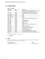
In addition, the Video Frame Buffer setting in the BIOS Setup
 |
View all Intel D865GRH manuals
Add to My Manuals
Save this manual to your list of manuals |
Page 64 highlights
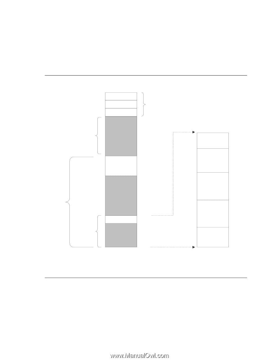
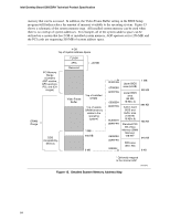
Intel Desktop Board D865GRH Technical Product Specification memory that can be accessed. In addition, the Video Frame Buffer setting in the BIOS Setup program will further reduce the amount of memory available to the operating system. Figure 15 shows a schematic of the system memory map. All installed system memory can be used when there is no overlap of system addresses. For example, all of the system address space can be utilized on a system that has 2 GB of installed system memory, AGP aperture set for 256 MB, and the PCI cards are requesting 200 MB of system address space. DRAM Range 4 GB Top of System Address Space PCI Memory Range (Contains AGP window, GFX aperture, PCI, and ICH ranges) FLASH APIC Reserved ~20 MB Video Frame Buffer Top of installed DRAM Top of usable DRAM (memory visible to the operating system) DOS Compatibility Memory 1 MB 640 KB 0 MB 0FFFFFH 0F0000H 0EFFFFH 0E0000H 0DFFFFH 0C0000H 0BFFFFH 0A0000H 09FFFFH 00000H Upper BIOS area (64 KB) Lower BIOS area (64 KB; 16 KB x 4) Add-in Card BIOS and Buffer area (128 KB; 16 KB x 8) Standard PCI/ ISA Video Memory (SMM Memory) 128 KB * DOS area (640 KB) 1 MB 960 KB 896 KB 768 KB 640 KB 0 KB * Optionally mapped to the internal AGP OM15972 Figure 15. Detailed System Memory Address Map 64
-
 1
1 -
2
-
3
-
4
-
5
-
6
-
7
-
8
-
9
-
10
-
11
-
12
-
13
-
14
-
15
-
16
-
17
-
18
-
19
-
20
-
21
-
22
-
23
-
24
-
25
-
26
-
27
-
28
-
29
-
30
-
31
-
32
-
33
-
34
-
35
-
36
-
37
-
38
-
39
-
40
-
41
-
42
-
43
-
44
-
45
-
46
-
47
-
48
-
49
-
50
-
51
-
52
-
53
-
54
-
55
-
56
-
57
-
58
-
 59
59 -
 60
60 -
 61
61 -
 62
62 -
 63
63 -
 64
64 -
 65
65 -
 66
66 -
 67
67 -
 68
68 -
 69
69 -
70
-
71
-
72
-
73
-
74
-
75
-
76
-
77
-
78
-
79
-
80
-
81
-
82
-
83
-
84
-
85
-
86
-
87
-
88
-
89
-
90
-
91
-
92
-
93
-
94
-
95
-
96
-
97
-
98
-
99
-
100
-
101
-
102
-
103
-
104
-
105
-
106
-
107
-
108
-
109
-
110
-
111
-
112
-
113
-
114
-
115
-
116
-
117
-
118
-
119
-
120
-
121
-
122
-
123
-
124
-
125
-
126
-
127
-
128
-
129
-
130
-
131
-
132
-
133
-
134
-
135
-
136
-
137
-
138
-
139
-
140
-
141
-
142
 |
 |