Intel D865GRH D865GRH_TechProdSpec. - Page 89
Electrical Considerations
 |
View all Intel D865GRH manuals
Add to My Manuals
Save this manual to your list of manuals |
Page 89 highlights
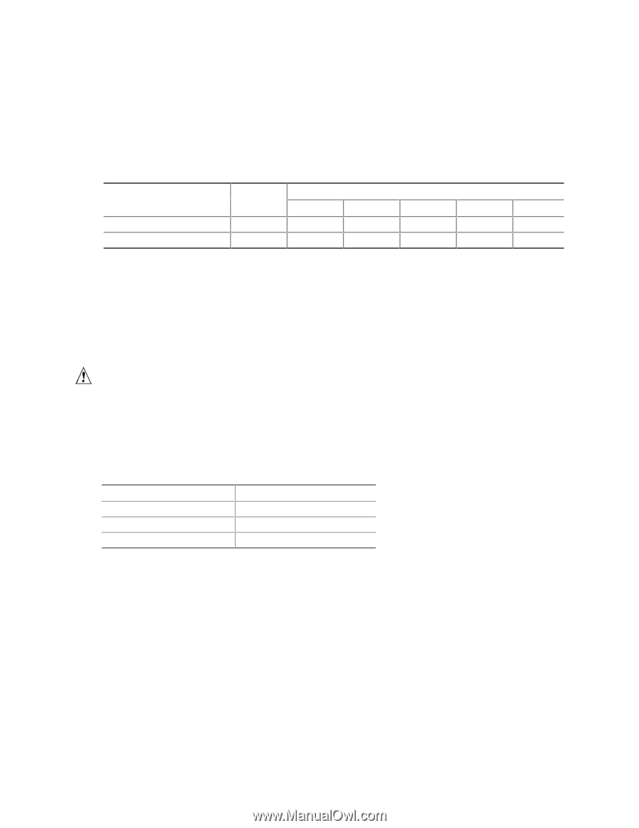
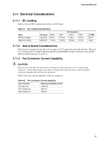
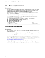
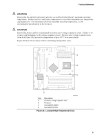
Technical Reference 2.11 Electrical Considerations 2.11.1 DC Loading Table 41 lists the DC loading characteristics of the board. Table 41. DC Loading Characteristics Mode Minimum loading Maximum loading DC Power 190.00 W 286.00 W +3.3 V 5.00 A 11.00 A +5 V 11.00 A 15.00 A DC Current at: +12 V -12 V 9.00 A 0.03 A 13.00 A 0.10 A +5 VSB 0.60 A 1.38 A 2.11.2 Add-in Board Considerations The boards are designed to provide 2 A (average) of +5 V current for each add-in board. The total +5 V current draw for a fully loaded Desktop Board D865GRH (all three expansion slots and the AGP slot filled) must not exceed 8 A. 2.11.3 Fan Connector Current Capability CAUTION The processor fan must be connected to the processor fan connector, not to a chassis fan connector. Connecting the processor fan to a chassis fan connector may result in onboard component damage that will halt fan operation. Table 42 lists the current capability of the fan connectors. Table 42. Fan Connector Current Capability Fan Connector Maximum Available Current Processor fan 1600 mA Front chassis fan 800 mA Rear chassis fan 800 mA 89
-
 1
1 -
2
-
3
-
4
-
5
-
6
-
7
-
8
-
9
-
10
-
11
-
12
-
13
-
14
-
15
-
16
-
17
-
18
-
19
-
20
-
21
-
22
-
23
-
24
-
25
-
26
-
27
-
28
-
29
-
30
-
31
-
32
-
33
-
34
-
35
-
36
-
37
-
38
-
39
-
40
-
41
-
42
-
43
-
44
-
45
-
46
-
47
-
48
-
49
-
50
-
51
-
52
-
53
-
54
-
55
-
56
-
57
-
58
-
59
-
60
-
61
-
62
-
63
-
64
-
65
-
66
-
67
-
68
-
69
-
70
-
71
-
72
-
73
-
74
-
75
-
76
-
77
-
78
-
79
-
80
-
81
-
82
-
83
-
 84
84 -
 85
85 -
 86
86 -
 87
87 -
 88
88 -
 89
89 -
 90
90 -
 91
91 -
 92
92 -
 93
93 -
 94
94 -
95
-
96
-
97
-
98
-
99
-
100
-
101
-
102
-
103
-
104
-
105
-
106
-
107
-
108
-
109
-
110
-
111
-
112
-
113
-
114
-
115
-
116
-
117
-
118
-
119
-
120
-
121
-
122
-
123
-
124
-
125
-
126
-
127
-
128
-
129
-
130
-
131
-
132
-
133
-
134
-
135
-
136
-
137
-
138
-
139
-
140
-
141
-
142
 |
 |