Intel D865GRH D865GRH_TechProdSpec. - Page 63

Technical Reference

Page 63 highlights

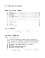
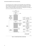
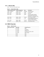
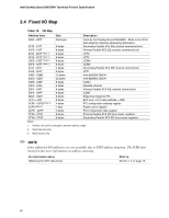
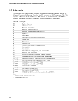
2 Technical Reference What This Chapter Contains 2.1 Introduction...63 2.2 Memory Resources ...63 2.3 DMA Channels ...65 2.4 Fixed I/O Map...66 2.5 PCI Configuration Space Map 67 2.6 Interrupts ...68 2.7 PCI Interrupt Routing Map 69 2.8 Connectors ...71 2.9 Jumper Blocks...85 2.10 Mechanical Considerations 87 2.11 Electrical Considerations 89 2.12 Thermal Considerations 90 2.13 Reliability ...93 2.14 Environmental ...93 2.15 Regulatory Compliance 94 2.1 Introduction Sections 2.2 - 2.6 contain several standalone tables. Table 17 describes the system memory map, Table 18 lists the DMA channels, Table 19 shows the I/O map, Table 20 defines the PCI configuration space map, and Table 22 describes the interrupts. The remaining sections in this chapter are introduced by text found with their respective section headings. 2.2 Memory Resources 2.2.1 Addressable Memory The board utilizes 4 GB of addressable system memory. Typically the address space that is allocated for PCI add-in cards, AGP aperture, BIOS (firmware hub), and chipset overhead resides above the top of DRAM (total system memory). On a system that has 4 GB of system memory installed, it is not possible to use all of the installed memory due to system address space being allocated for other system critical functions. These functions include the following: • Memory-mapped I/O that is dynamically allocated for PCI and AGP cards • AGP aperture • APIC and chipset overhead (approximately 18 MB) • BIOS/firmware hub (approximately 2 MB) The amount of installed memory that can be used will vary based on add-in cards and BIOS settings. For example, if the PCI cards are requesting 200 MB of system memory and the AGP aperture is set to 256 MB in the BIOS Setup program, there will be approximately 3.54 GB of 63

  • 1
  • 2
  • 3
  • 4
  • 5
  • 6
  • 7
  • 8
  • 9
  • 10
  • 11
  • 12
  • 13
  • 14
  • 15
  • 16
  • 17
  • 18
  • 19
  • 20
  • 21
  • 22
  • 23
  • 24
  • 25
  • 26
  • 27
  • 28
  • 29
  • 30
  • 31
  • 32
  • 33
  • 34
  • 35
  • 36
  • 37
  • 38
  • 39
  • 40
  • 41
  • 42
  • 43
  • 44
  • 45
  • 46
  • 47
  • 48
  • 49
  • 50
  • 51
  • 52
  • 53
  • 54
  • 55
  • 56
  • 57
  • 58
  • 59
  • 60
  • 61
  • 62
  • 63
  • 64
  • 65
  • 66
  • 67
  • 68
  • 69
  • 70
  • 71
  • 72
  • 73
  • 74
  • 75
  • 76
  • 77
  • 78
  • 79
  • 80
  • 81
  • 82
  • 83
  • 84
  • 85
  • 86
  • 87
  • 88
  • 89
  • 90
  • 91
  • 92
  • 93
  • 94
  • 95
  • 96
  • 97
  • 98
  • 99
  • 100
  • 101
  • 102
  • 103
  • 104
  • 105
  • 106
  • 107
  • 108
  • 109
  • 110
  • 111
  • 112
  • 113
  • 114
  • 115
  • 116
  • 117
  • 118
  • 119
  • 120
  • 121
  • 122
  • 123
  • 124
  • 125
  • 126
  • 127
  • 128
  • 129
  • 130
  • 131
  • 132
  • 133
  • 134
  • 135
  • 136
  • 137
  • 138
  • 139
  • 140
  • 141
  • 142

63
2 Technical Reference
What This Chapter Contains
2.1
Introduction
.................................................................................................................
63
2.2
Memory Resources
....................................................................................................
63
2.3
DMA Channels
...........................................................................................................
65
2.4
Fixed I/O Map
.............................................................................................................
66
2.5
PCI Configuration Space Map
....................................................................................
67
2.6
Interrupts
....................................................................................................................
68
2.7
PCI Interrupt Routing Map
..........................................................................................
69
2.8
Connectors
.................................................................................................................
71
2.9
Jumper Blocks
............................................................................................................
85
2.10
Mechanical Considerations
.........................................................................................
87
2.11
Electrical Considerations
............................................................................................
89
2.12
Thermal Considerations
..............................................................................................
90
2.13
Reliability
....................................................................................................................
93
2.14
Environmental
............................................................................................................
93
2.15
Regulatory Compliance
..............................................................................................
94
2.1 Introduction
Sections 2.2 - 2.6 contain several standalone tables.
Table 17 describes the system memory map,
Table 18 lists the DMA channels, Table 19 shows the I/O map, Table 20 defines the PCI
configuration space map, and Table 22 describes the interrupts.
The remaining sections in this
chapter are introduced by text found with their respective section headings.
2.2 Memory Resources
2.2.1
Addressable Memory
The board utilizes 4 GB of addressable system memory.
Typically the address space that is
allocated for PCI add-in cards, AGP aperture, BIOS (firmware hub), and chipset overhead resides
above the top of DRAM (total system memory).
On a system that has 4 GB of system memory
installed, it is not possible to use all of the installed memory due to system address space being
allocated for other system critical functions.
These functions include the following:
Memory-mapped I/O that is dynamically allocated for PCI and AGP cards
AGP aperture
APIC and chipset overhead (approximately 18 MB)
BIOS/firmware hub (approximately 2 MB)
The amount of installed memory that can be used will vary based on add-in cards and BIOS
settings.
For example, if the PCI cards are requesting 200 MB of system memory and the AGP
aperture is set to 256 MB in the BIOS Setup program, there will be approximately 3.54 GB of