Intel D865GRH D865GRH_TechProdSpec. - Page 73
Internal I/O Connectors
 |
View all Intel D865GRH manuals
Add to My Manuals
Save this manual to your list of manuals |
Page 73 highlights
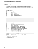
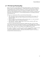
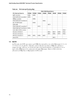
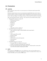
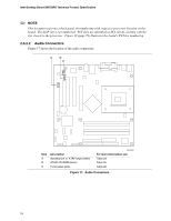
Technical Reference ✏ NOTE The back panel audio line out connector is designed to power headphones or amplified speakers only. Poor audio quality occurs if passive (non-amplified) speakers are connected to this output. 2.8.2 Internal I/O Connectors The internal I/O connectors are divided into the following functional groups: • Audio (see page 74) Auxiliary line in ATAPI CD-ROM Front panel audio • Power and hardware control (see page 76) Fans [3] ATX12V power Main power Chassis intrusion • Add-in boards and peripheral interfaces (see page 79) PCI bus AGP Parallel ATA IDE Diskette drive SCSI hard drive activity LED (optional) Serial ATA 2.8.2.1 Expansion Slots The board has the following expansion slots: • AGP connector: The AGP connector is keyed for Universal 0.8 V AGP 3.0 cards or 1.5 V AGP 2.0 cards only. Do not install a legacy 3.3 V AGP card. The AGP connector is not mechanically compatible with legacy 3.3 V AGP cards. • Three PCI rev 2.2 compliant local bus slots. The SMBus is routed to PCI bus connector 2 only (ATX expansion slot 6). PCI add-in cards with SMBus support can access sensor data and other information residing on the board. ✏ NOTE The SMBus routing to the PCI bus connectors does not conform to the PCI Engineering Change Notice (ECN) "Addition of the SMBus to the PCI Connector ECN", dated October 5th, 2000. The ECN specifies that SMBus signals must be routed to all PCI bus connectors. On this board, SMBus signals are routed to PCI bus connector 2 only. Add-in cards that implement PCI bus connector pins A40 and A41 for any purpose other than SMBCLK (SMBus clock) and SMBDAT (SMBus data) should not be installed in PCI bus connector 2. For information about Addition of the SMBus to the PCI Connector ECN Refer to http://www.pcisig.com/data/specifications/smb_ecn_04 0501.pdf 73
-
 1
1 -
2
-
3
-
4
-
5
-
6
-
7
-
8
-
9
-
10
-
11
-
12
-
13
-
14
-
15
-
16
-
17
-
18
-
19
-
20
-
21
-
22
-
23
-
24
-
25
-
26
-
27
-
28
-
29
-
30
-
31
-
32
-
33
-
34
-
35
-
36
-
37
-
38
-
39
-
40
-
41
-
42
-
43
-
44
-
45
-
46
-
47
-
48
-
49
-
50
-
51
-
52
-
53
-
54
-
55
-
56
-
57
-
58
-
59
-
60
-
61
-
62
-
63
-
64
-
65
-
66
-
67
-
 68
68 -
 69
69 -
 70
70 -
 71
71 -
 72
72 -
 73
73 -
 74
74 -
 75
75 -
 76
76 -
 77
77 -
 78
78 -
79
-
80
-
81
-
82
-
83
-
84
-
85
-
86
-
87
-
88
-
89
-
90
-
91
-
92
-
93
-
94
-
95
-
96
-
97
-
98
-
99
-
100
-
101
-
102
-
103
-
104
-
105
-
106
-
107
-
108
-
109
-
110
-
111
-
112
-
113
-
114
-
115
-
116
-
117
-
118
-
119
-
120
-
121
-
122
-
123
-
124
-
125
-
126
-
127
-
128
-
129
-
130
-
131
-
132
-
133
-
134
-
135
-
136
-
137
-
138
-
139
-
140
-
141
-
142
 |
 |