Intel D865GRH D865GRH_TechProdSpec. - Page 75
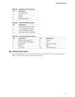
Table 24., Auxiliary Line In Connector, Table 25., ATAPI CD-ROM Connector, Table 26., Front Panel
 |
View all Intel D865GRH manuals
Add to My Manuals
Save this manual to your list of manuals |
Page 75 highlights
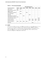
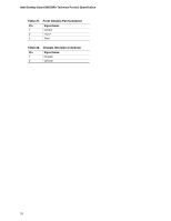
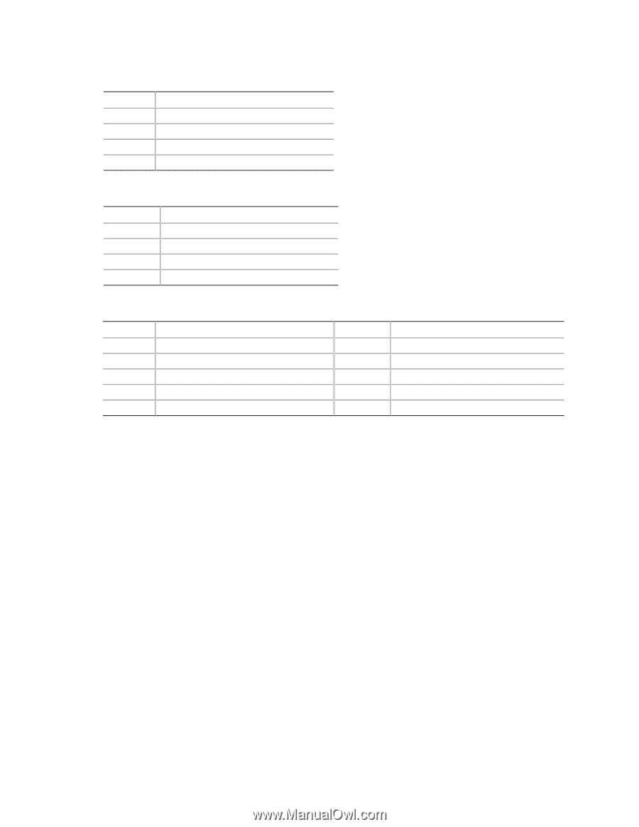
Technical Reference Table 24. Auxiliary Line In Connector Pin Signal Name 1 Left auxiliary line in 2 Ground 3 Ground 4 Right auxiliary line in Table 25. ATAPI CD-ROM Connector Pin Signal Name 1 Left audio input from CD-ROM 2 CD audio differential ground 3 CD audio differential ground 4 Right audio input from CD-ROM Table 26. Front Panel Audio Connector Pin Signal Name Pin 1 Mono Mic in (Stereo Mic 1) 2 3 Mono Mic Bias (Stereo Mic 2) 4 5 RIGHT_OUT 6 7 Ground 8 9 LEFT_OUT 10 Signal Name Ground +5 V Right channel return Key Left channel return # INTEGRATOR'S NOTE The front panel audio connector is alternately used as a jumper block for routing audio signals. Refer to Section 2.9.1 on page 85 for more information. 75
-
 1
1 -
2
-
3
-
4
-
5
-
6
-
7
-
8
-
9
-
10
-
11
-
12
-
13
-
14
-
15
-
16
-
17
-
18
-
19
-
20
-
21
-
22
-
23
-
24
-
25
-
26
-
27
-
28
-
29
-
30
-
31
-
32
-
33
-
34
-
35
-
36
-
37
-
38
-
39
-
40
-
41
-
42
-
43
-
44
-
45
-
46
-
47
-
48
-
49
-
50
-
51
-
52
-
53
-
54
-
55
-
56
-
57
-
58
-
59
-
60
-
61
-
62
-
63
-
64
-
65
-
66
-
67
-
68
-
69
-
 70
70 -
 71
71 -
 72
72 -
 73
73 -
 74
74 -
 75
75 -
 76
76 -
 77
77 -
 78
78 -
 79
79 -
 80
80 -
81
-
82
-
83
-
84
-
85
-
86
-
87
-
88
-
89
-
90
-
91
-
92
-
93
-
94
-
95
-
96
-
97
-
98
-
99
-
100
-
101
-
102
-
103
-
104
-
105
-
106
-
107
-
108
-
109
-
110
-
111
-
112
-
113
-
114
-
115
-
116
-
117
-
118
-
119
-
120
-
121
-
122
-
123
-
124
-
125
-
126
-
127
-
128
-
129
-
130
-
131
-
132
-
133
-
134
-
135
-
136
-
137
-
138
-
139
-
140
-
141
-
142
 |
 |
Technical Reference
75
Table 24.
Auxiliary Line In Connector
Pin
Signal Name
1
Left auxiliary line in
2
Ground
3
Ground
4
Right auxiliary line in
Table 25.
ATAPI CD-ROM Connector
Pin
Signal Name
1
Left audio input from CD-ROM
2
CD audio differential ground
3
CD audio differential ground
4
Right audio input from CD-ROM
Table 26.
Front Panel Audio Connector
Pin
Signal Name
Pin
Signal Name
1
Mono Mic in (Stereo Mic 1)
2
Ground
3
Mono Mic Bias
(Stereo Mic 2)
4
+5 V
5
RIGHT_OUT
6
Right channel return
7
Ground
8
Key
9
LEFT_OUT
10
Left channel return
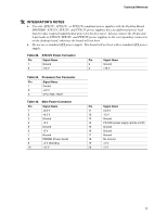
#
INTEGRATOR
’
S NOTE
The front panel audio connector is alternately used as a jumper block for routing audio signals.
Refer to Section 2.9.1 on page 85 for more information.