Intel D865GRH D865GRH_TechProdSpec. - Page 52
Fan Connectors, 12.2.3, LAN Wake Capabilities, CAUTION
 |
View all Intel D865GRH manuals
Add to My Manuals
Save this manual to your list of manuals |
Page 52 highlights
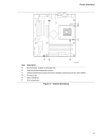
Intel Desktop Board D865GRH Technical Product Specification 1.12.2.2 Fan Connectors Table 16 summarizes the function/operation of the fan connectors. Table 16. Fan Connector Function/Operation Connector Processor fan Front chassis fan Rear chassis fan Description • +12 V DC connection for a processor fan or active fan heatsink. • Fan is on in the S0 or S1 state. Fan is off when the system is off or in the S3, S4, or S5 state. • Wired to a fan tachometer input of the hardware monitoring and fan control ASIC. • Closed-loop fan control that can adjust the fan speed or switch the fans on or off as needed. • +12 V DC connection for a system or chassis fan. • Fan is on in the S0 or S1 state. Fan is off when the system is off or in the S3, S4, or S5 state. • Wired to a fan tachometer input of the hardware monitoring and fan control ASIC. • Closed-loop fan control that can adjust the fan speed or switch the fans on or off as needed. • +12 V DC connection for a system or chassis fan. • Fan is on in the S0 or S1 state. Fan is off when the system is off or in the S3, S4, or S5 state. • Wired to a fan tachometer input of the hardware monitoring and fan control ASIC. • Closed-loop fan control that can adjust the fan speed or switch the fans on or off as needed. For information about The location of the fan connectors The location of the fan connectors and sensors for thermal monitoring The signal names of the fan connectors Refer to Figure 17, page 74 Figure 13, on page 47 Section 2.8.2.2, page 74 1.12.2.3 LAN Wake Capabilities CAUTION For LAN wake capabilities, the +5 V standby line for the power supply must be capable of providing adequate +5 V standby current. Failure to provide adequate standby current when implementing LAN wake capabilities can damage the power supply. LAN wake capabilities enable remote wake-up of the computer through a network. The LAN subsystem PCI bus network adapter monitors network traffic at the Media Independent Interface. Upon detecting a Magic Packet* frame, the LAN subsystem asserts a wake-up signal that powers up the computer. Depending on the LAN implementation, the Desktop Board D865GRH supports LAN wake capabilities with ACPI in the following ways: • The PCI bus PME# signal for PCI 2.2 compliant LAN designs • The onboard LAN subsystem 52
-
 1
1 -
2
-
3
-
4
-
5
-
6
-
7
-
8
-
9
-
10
-
11
-
12
-
13
-
14
-
15
-
16
-
17
-
18
-
19
-
20
-
21
-
22
-
23
-
24
-
25
-
26
-
27
-
28
-
29
-
30
-
31
-
32
-
33
-
34
-
35
-
36
-
37
-
38
-
39
-
40
-
41
-
42
-
43
-
44
-
45
-
46
-
 47
47 -
 48
48 -
 49
49 -
 50
50 -
 51
51 -
 52
52 -
 53
53 -
 54
54 -
 55
55 -
 56
56 -
 57
57 -
58
-
59
-
60
-
61
-
62
-
63
-
64
-
65
-
66
-
67
-
68
-
69
-
70
-
71
-
72
-
73
-
74
-
75
-
76
-
77
-
78
-
79
-
80
-
81
-
82
-
83
-
84
-
85
-
86
-
87
-
88
-
89
-
90
-
91
-
92
-
93
-
94
-
95
-
96
-
97
-
98
-
99
-
100
-
101
-
102
-
103
-
104
-
105
-
106
-
107
-
108
-
109
-
110
-
111
-
112
-
113
-
114
-
115
-
116
-
117
-
118
-
119
-
120
-
121
-
122
-
123
-
124
-
125
-
126
-
127
-
128
-
129
-
130
-
131
-
132
-
133
-
134
-
135
-
136
-
137
-
138
-
139
-
140
-
141
-
142
 |
 |