Intel D865GRH D865GRH_TechProdSpec. - Page 86
BIOS Setup Configuration Jumper Block
 |
View all Intel D865GRH manuals
Add to My Manuals
Save this manual to your list of manuals |
Page 86 highlights
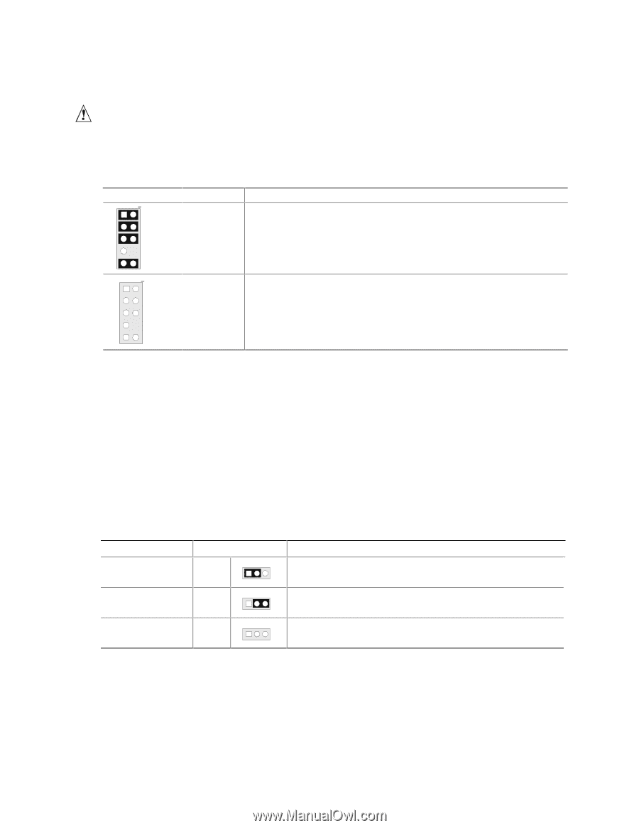
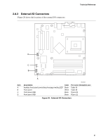
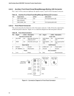
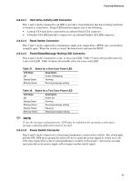
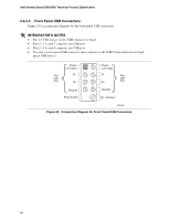
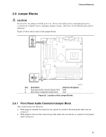
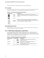
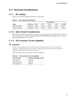
Intel Desktop Board D865GRH Technical Product Specification Table 39 describes the two configurations of this connector/jumper block. CAUTION Do not place jumpers on this block in any configuration other than the one described in Table 39. Other jumper configurations are not supported and could damage the Desktop Board. Table 39. Front Panel Audio Connector/Jumper Block Jumper Setting 1 2 3 4 5 6 7 9 10 1 and 2 3 and 4 5 and 6 9 and 10 Configuration Audio line out signals are routed to the back panel audio line out connector. The back panel audio line out connector is shown in Figure 16 on page 72. 1 2 3 4 5 6 7 9 10 No jumpers installed Audio line out and mic in signals are available for front panel audio connectors. Table 26 on page 75 lists the names of the signals available on this connector when no jumpers are installed. # INTEGRATOR'S NOTE When the jumpers are removed and this connector is used for front panel audio, the back panel audio line out and mic in connectors are disabled. 2.9.2 BIOS Setup Configuration Jumper Block The 3-pin jumper block determines the BIOS Setup program's mode. Table 40 describes the jumper settings for the three modes: normal, configure, and recovery. When the jumper is set to configure mode and the computer is powered-up, the BIOS compares the processor version and the microcode version in the BIOS and reports if the two match. Table 40. BIOS Setup Configuration Jumper Settings Function/Mode Normal Jumper Setting 1-2 1 3 Configuration The BIOS uses current configuration information and passwords for booting. Configure 2-3 1 After the POST runs, Setup runs automatically. The 3 maintenance menu is displayed. Recovery None 1 The BIOS attempts to recover the BIOS configuration. A 3 recovery diskette is required. 86
-
 1
1 -
2
-
3
-
4
-
5
-
6
-
7
-
8
-
9
-
10
-
11
-
12
-
13
-
14
-
15
-
16
-
17
-
18
-
19
-
20
-
21
-
22
-
23
-
24
-
25
-
26
-
27
-
28
-
29
-
30
-
31
-
32
-
33
-
34
-
35
-
36
-
37
-
38
-
39
-
40
-
41
-
42
-
43
-
44
-
45
-
46
-
47
-
48
-
49
-
50
-
51
-
52
-
53
-
54
-
55
-
56
-
57
-
58
-
59
-
60
-
61
-
62
-
63
-
64
-
65
-
66
-
67
-
68
-
69
-
70
-
71
-
72
-
73
-
74
-
75
-
76
-
77
-
78
-
79
-
80
-
 81
81 -
 82
82 -
 83
83 -
 84
84 -
 85
85 -
 86
86 -
 87
87 -
 88
88 -
 89
89 -
 90
90 -
 91
91 -
92
-
93
-
94
-
95
-
96
-
97
-
98
-
99
-
100
-
101
-
102
-
103
-
104
-
105
-
106
-
107
-
108
-
109
-
110
-
111
-
112
-
113
-
114
-
115
-
116
-
117
-
118
-
119
-
120
-
121
-
122
-
123
-
124
-
125
-
126
-
127
-
128
-
129
-
130
-
131
-
132
-
133
-
134
-
135
-
136
-
137
-
138
-
139
-
140
-
141
-
142
 |
 |