Intel D925XHY D925XHY Technical Product Specification - Page 20
Single Channel Asymmetric Mode Configurations
 |
View all Intel D925XHY manuals
Add to My Manuals
Save this manual to your list of manuals |
Page 20 highlights
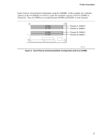
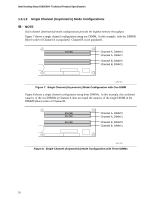
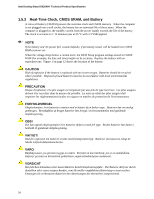
Intel Desktop Board D925XHY Technical Product Specification 1.4.1.2 Single Channel (Asymmetric) Mode Configurations NOTE Dual channel (Interleaved) mode configurations provide the highest memory throughput. Figure 7 shows a single channel configuration using one DIMM. In this example, only the DIMM0 (blue) socket of Channel A is populated. Channel B is not populated. 256 MB Channel A, DIMM 0 Channel A, DIMM 1 Channel B, DIMM 0 Channel B, DIMM 1 OM17125 Figure 7. Single Channel (Asymmetric) Mode Configuration with One DIMM Figure 8 shows a single channel configuration using three DIMMs. In this example, the combined capacity of the two DIMMs in Channel A does not equal the capacity of the single DIMM in the DIMM0 (blue) socket of Channel B. 256 MB 512 MB 512 MB Channel A, DIMM 0 Channel A, DIMM 1 Channel B, DIMM 0 Channel B, DIMM 1 OM17126 Figure 8. Single Channel (Asymmetric) Mode Configuration with Three DIMMs 20
-
 1
1 -
2
-
3
-
4
-
5
-
6
-
7
-
8
-
9
-
10
-
11
-
12
-
13
-
14
-
 15
15 -
 16
16 -
 17
17 -
 18
18 -
 19
19 -
 20
20 -
 21
21 -
 22
22 -
 23
23 -
 24
24 -
 25
25 -
26
-
27
-
28
-
29
-
30
-
31
-
32
-
33
-
34
-
35
-
36
-
37
-
38
-
39
-
40
-
41
-
42
-
43
-
44
-
45
-
46
-
47
-
48
-
49
-
50
-
51
-
52
-
53
-
54
-
55
-
56
-
57
-
58
-
59
-
60
-
61
-
62
-
63
-
64
-
65
-
66
-
67
-
68
-
69
-
70
-
71
-
72
-
73
-
74
-
75
-
76
-
77
-
78
-
79
-
80
-
81
-
82
-
83
-
84
-
85
-
86
-
87
-
88
-
89
-
90
-
91
-
92
 |
 |
