Intel D925XHY D925XHY Technical Product Specification - Page 7

Error Messages and Beep Codes, s, Tables

Page 7 highlights

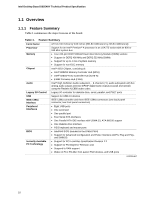
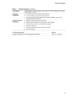
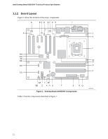
Contents 4 Error Messages and Beep Codes 4.1 BIOS Error Messages 85 4.2 Port 80h POST Codes 87 4.3 Bus Initialization Checkpoints 91 4.4 Speaker ...92 4.5 BIOS Beep Codes...92 Figures 1. Desktop Board D925XHY Components 12 2. Block Diagram...14 3. Memory Channel and DIMM Configuration 17 4. Dual Channel (Interleaved) Mode Configuration with Two DIMMs 18 5. Dual Channel (Interleaved) Mode Configuration with Three DIMMs 18 6. Dual Channel (Interleaved) Mode Configuration with Four DIMMs 19 7. Single Channel (Asymmetric) Mode Configuration with One DIMM 20 8. Single Channel (Asymmetric) Mode Configuration with Three DIMMs 20 9. Front/Back Panel Audio Connector Options 31 10. 8-channel (7.1) Audio Subsystem Block Diagram 31 11. LAN Connector LED Locations 32 12. Sensors and Fan Connectors 34 13. Location of the Standby Power Indicator LED 41 14. Detailed System Memory Address Map 44 15. Back Panel Connectors 50 16. Component-side Connectors 52 17. Connection Diagram for Front Panel Connector 58 18. Connection Diagram for Front Panel USB Connectors 60 19. Connection Diagram for IEEE 1394a Connectors 60 20. Location of the Jumper Block 61 21. Board Dimensions...62 22. I/O Shield Dimensions 63 23. Processor Heatsink for Omni-directional Airflow 66 24. Localized High Temperature Zones 67 Tables 1. Feature Summary ...10 2. D925XHY Components Shown in Figure 1 13 3. Supported Memory Configurations 16 4. LAN Connector LED States 32 5. Effects of Pressing the Power Switch 36 6. Power States and Targeted System Power 37 7. Wake-up Devices and Events 38 8. System Memory Map 45 9. DMA Channels ...45 10. I/O Map ...46 11. PCI Configuration Space Map 47 12. Interrupts ...48 13. PCI Interrupt Routing Map 49 14. Back Panel Connectors Shown in Figure 15 51 vii

  • 1
  • 2
  • 3
  • 4
  • 5
  • 6
  • 7
  • 8
  • 9
  • 10
  • 11
  • 12
  • 13
  • 14
  • 15
  • 16
  • 17
  • 18
  • 19
  • 20
  • 21
  • 22
  • 23
  • 24
  • 25
  • 26
  • 27
  • 28
  • 29
  • 30
  • 31
  • 32
  • 33
  • 34
  • 35
  • 36
  • 37
  • 38
  • 39
  • 40
  • 41
  • 42
  • 43
  • 44
  • 45
  • 46
  • 47
  • 48
  • 49
  • 50
  • 51
  • 52
  • 53
  • 54
  • 55
  • 56
  • 57
  • 58
  • 59
  • 60
  • 61
  • 62
  • 63
  • 64
  • 65
  • 66
  • 67
  • 68
  • 69
  • 70
  • 71
  • 72
  • 73
  • 74
  • 75
  • 76
  • 77
  • 78
  • 79
  • 80
  • 81
  • 82
  • 83
  • 84
  • 85
  • 86
  • 87
  • 88
  • 89
  • 90
  • 91
  • 92

Contents
vii
4
Error Messages and Beep Codes
4.1
BIOS Error Messages
..................................................................................................
85
4.2
Port 80h POST Codes
.................................................................................................
87
4.3
Bus Initialization Checkpoints
......................................................................................
91
4.4
Speaker
.......................................................................................................................
92
4.5
BIOS Beep Codes
........................................................................................................
92
Figures
1.
Desktop Board D925XHY Components
.......................................................................
12
2.
Block Diagram
..............................................................................................................
14
3.
Memory Channel and DIMM Configuration
..................................................................
17
4.
Dual Channel (Interleaved) Mode Configuration with Two DIMMs
..............................
18
5.
Dual Channel (Interleaved) Mode Configuration with Three DIMMs
............................
18
6.
Dual Channel (Interleaved) Mode Configuration with Four DIMMs
..............................
19
7.
Single Channel (Asymmetric) Mode Configuration with One DIMM
.............................
20
8.
Single Channel (Asymmetric) Mode Configuration with Three DIMMs
........................
20
9.
Front/Back Panel Audio Connector Options
................................................................
31
10.
8-channel (7.1) Audio Subsystem Block Diagram
........................................................
31
11.
LAN Connector LED Locations
....................................................................................
32
12.
Sensors and Fan Connectors
......................................................................................
34
13.
Location of the Standby Power Indicator LED
.............................................................
41
14.
Detailed System Memory Address Map
.......................................................................
44
15.
Back Panel Connectors
................................................................................................
50
16.
Component-side Connectors
.......................................................................................
52
17.
Connection Diagram for Front Panel Connector
..........................................................
58
18.
Connection Diagram for Front Panel USB Connectors
................................................
60
19.
Connection Diagram for IEEE 1394a Connectors
........................................................
60
20.
Location of the Jumper Block
.......................................................................................
61
21.
Board Dimensions
........................................................................................................
62
22.
I/O Shield Dimensions
..................................................................................................
63
23.
Processor Heatsink for Omni-directional Airflow
..........................................................
66
24.
Localized High Temperature Zones
.............................................................................
67
Tables
1.
Feature Summary
........................................................................................................
10
2.
D925XHY Components Shown in Figure 1
..................................................................
13
3.
Supported Memory Configurations
..............................................................................
16
4.
LAN Connector LED States
.........................................................................................
32
5.
Effects of Pressing the Power Switch
..........................................................................
36
6.
Power States and Targeted System Power
.................................................................
37
7.
Wake-up Devices and Events
......................................................................................
38
8.
System Memory Map
...................................................................................................
45
9.
DMA Channels
.............................................................................................................
45
10.
I/O Map
........................................................................................................................
46
11.
PCI Configuration Space Map
......................................................................................
47
12.
Interrupts
......................................................................................................................
48
13.
PCI Interrupt Routing Map
...........................................................................................
49
14.
Back Panel Connectors Shown in Figure 15
................................................................
51