Intel D925XHY D925XHY Technical Product Specification - Page 39
Power Connector, 11.2.2, Fan Connectors, 11.2.3, LAN Wake Capabilities, CAUTION
 |
View all Intel D925XHY manuals
Add to My Manuals
Save this manual to your list of manuals |
Page 39 highlights
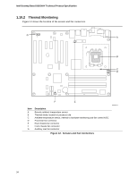
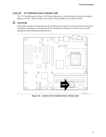
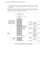
Product Description NOTE The use of Resume on Ring and Wake from USB technologies from an ACPI state requires an operating system that provides full ACPI support. 1.11.2.1 Power Connector ATX12V-compliant power supplies can turn off the system power through system control. When an ACPI-enabled system receives the correct command, the power supply removes all non-standby voltages. When resuming from an AC power failure, the computer returns to the power state it was in before power was interrupted (on or off). The computer's response can be set using the Last Power State feature in the BIOS Setup program's Boot menu. For information about The location of the power connector The signal names of the power connector Refer to Figure 16, page 52 Table 21, page 56 1.11.2.2 Fan Connectors The function/operation of the fan connectors is as follows: • The fans are on when the board is in the S0 or S1 state. • The fans are off when the board is off or in the S3, S4, or S5 state. • Each fan connector is wired to a fan tachometer input of the hardware monitoring and fan control ASIC • All fan connectors support closed-loop fan control that can adjust the fan speed or switch the fan on or off as needed. • All fan connectors have a +12 V DC connection For information about The location of the fan connectors The location of the fan connectors and sensors for thermal monitoring The signal names of the fan connectors Refer to Figure 16, page 52 Figure 12, page 34 Section 2.8.2, page 52 1.11.2.3 LAN Wake Capabilities CAUTION For LAN wake capabilities, the +5 V standby line for the power supply must be capable of providing adequate +5 V standby current. Failure to provide adequate standby current when implementing LAN wake capabilities can damage the power supply. LAN wake capabilities enable remote wake-up of the computer through a network. The LAN network adapter monitors network traffic at the Media Independent Interface. Upon detecting a Magic Packet* frame, the LAN subsystem asserts a wake-up signal that powers up the computer. Depending on the LAN implementation, the board supports LAN wake capabilities with ACPI in the following ways: • The PCI Express WAKE# signal 39
-
 1
1 -
2
-
3
-
4
-
5
-
6
-
7
-
8
-
9
-
10
-
11
-
12
-
13
-
14
-
15
-
16
-
17
-
18
-
19
-
20
-
21
-
22
-
23
-
24
-
25
-
26
-
27
-
28
-
29
-
30
-
31
-
32
-
33
-
 34
34 -
 35
35 -
 36
36 -
 37
37 -
 38
38 -
 39
39 -
 40
40 -
 41
41 -
 42
42 -
 43
43 -
 44
44 -
45
-
46
-
47
-
48
-
49
-
50
-
51
-
52
-
53
-
54
-
55
-
56
-
57
-
58
-
59
-
60
-
61
-
62
-
63
-
64
-
65
-
66
-
67
-
68
-
69
-
70
-
71
-
72
-
73
-
74
-
75
-
76
-
77
-
78
-
79
-
80
-
81
-
82
-
83
-
84
-
85
-
86
-
87
-
88
-
89
-
90
-
91
-
92
 |
 |
