Intel D925XHY D925XHY Technical Product Specification - Page 77

What This Contains

Page 77 highlights

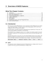
3 Overview of BIOS Features What This Chapter Contains 3.1 Introduction ...77 3.2 BIOS Flash Memory Organization 78 3.3 Resource Configuration 78 3.4 System Management BIOS (SMBIOS 79 3.5 Legacy USB Support...79 3.6 BIOS Updates ...80 3.7 Boot Options ...81 3.8 Fast Booting Systems with Intel® Rapid BIOS Boot 82 3.9 BIOS Security Features 83 3.1 Introduction The boards uses an Intel/AMI BIOS that is stored in the Firmware Hub (FWH) and can be updated using a disk-based program. The FWH contains the BIOS Setup program, POST, the PCI autoconfiguration utility, and Plug and Play support. The BIOS displays a message during POST identifying the type of BIOS and a revision code. The initial production BIOSs are identified as CV92510A.86A. When the BIOS Setup configuration jumper is set to configure mode and the computer is poweredup, the BIOS compares the CPU version and the microcode version in the BIOS and reports if the two match. The BIOS Setup program can be used to view and change the BIOS settings for the computer. The BIOS Setup program is accessed by pressing the key after the Power-On Self-Test (POST) memory test begins and before the operating system boot begins. The menu bar is shown below. Maintenance Main Advanced Security Power Boot Exit NOTE The maintenance menu is displayed only when the Desktop Board is in configure mode. Section 2.9 on page 61 shows how to put the Desktop Board in configure mode. 77

  • 1
  • 2
  • 3
  • 4
  • 5
  • 6
  • 7
  • 8
  • 9
  • 10
  • 11
  • 12
  • 13
  • 14
  • 15
  • 16
  • 17
  • 18
  • 19
  • 20
  • 21
  • 22
  • 23
  • 24
  • 25
  • 26
  • 27
  • 28
  • 29
  • 30
  • 31
  • 32
  • 33
  • 34
  • 35
  • 36
  • 37
  • 38
  • 39
  • 40
  • 41
  • 42
  • 43
  • 44
  • 45
  • 46
  • 47
  • 48
  • 49
  • 50
  • 51
  • 52
  • 53
  • 54
  • 55
  • 56
  • 57
  • 58
  • 59
  • 60
  • 61
  • 62
  • 63
  • 64
  • 65
  • 66
  • 67
  • 68
  • 69
  • 70
  • 71
  • 72
  • 73
  • 74
  • 75
  • 76
  • 77
  • 78
  • 79
  • 80
  • 81
  • 82
  • 83
  • 84
  • 85
  • 86
  • 87
  • 88
  • 89
  • 90
  • 91
  • 92

77
3
Overview of BIOS Features
What This Chapter Contains
3.1
Introduction
..................................................................................................................
77
3.2
BIOS Flash Memory Organization
...............................................................................
78
3.3
Resource Configuration
...............................................................................................
78
3.4
System Management BIOS (SMBIOS)
........................................................................
79
3.5
Legacy USB Support
....................................................................................................
79
3.6
BIOS Updates
..............................................................................................................
80
3.7
Boot Options
................................................................................................................
81
3.8
Fast Booting Systems with Intel
®
Rapid BIOS Boot
.....................................................
82
3.9
BIOS Security Features
...............................................................................................
83
3.1 Introduction
The boards uses an Intel/AMI BIOS that is stored in the Firmware Hub (FWH) and can be updated
using a disk-based program.
The FWH contains the BIOS Setup program, POST, the PCI auto-
configuration utility, and Plug and Play support.
The BIOS displays a message during POST identifying the type of BIOS and a revision code.
The
initial production BIOSs are identified as CV92510A.86A.
When the BIOS Setup configuration jumper is set to configure mode and the computer is powered-
up, the BIOS compares the CPU version and the microcode version in the BIOS and reports if the
two match.
The BIOS Setup program can be used to view and change the BIOS settings for the computer.
The
BIOS Setup program is accessed by pressing the <F2> key after the Power-On Self-Test (POST)
memory test begins and before the operating system boot begins.
The menu bar is shown below.
Maintenance
Main
Advanced
Security
Power
Boot
Exit
±
NOTE
The maintenance menu is displayed only when the Desktop Board is in configure mode. Section 2.9
on page 61 shows how to put the Desktop Board in configure mode.