Intel D925XHY D925XHY Technical Product Specification - Page 37
System States and Power States, 11.1.2, One-Watt Standby
 |
View all Intel D925XHY manuals
Add to My Manuals
Save this manual to your list of manuals |
Page 37 highlights
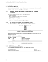
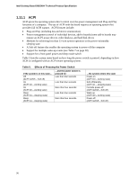
Product Description 1.11.1.1 System States and Power States Under ACPI, the operating system directs all system and device power state transitions. The operating system puts devices in and out of low-power states based on user preferences and knowledge of how devices are being used by applications. Devices that are not being used can be turned off. The operating system uses information from applications and user settings to put the system as a whole into a low-power state. Table 6 lists the power states supported by the board along with the associated system power targets. See the ACPI specification for a complete description of the various system and power states. Table 6. Power States and Targeted System Power Global States G0 - working state G1 - sleeping state G1 - sleeping state G1 - sleeping state G2/S5 G3 - mechanical off AC power is disconnected from the computer. Sleeping States S0 - working S1 - Processor stopped S3 - Suspend to RAM. Context saved to RAM. S4 - Suspend to disk. Context saved to disk. S5 - Soft off. Context not saved. Cold boot is required. No power to the system. Processor States C0 - working C1 - stop grant No power No power No power Device States D0 - working state. D1, D2, D3 - device specification specific. D3 - no power except for wake-up logic. D3 - no power except for wake-up logic. D3 - no power except for wake-up logic. Targeted System Power (Note 1) Full power > 30 W 5 W < power < 52.5 W Power < 5 W (Note 2) Power < 5 W (Note 2) Power < 5 W (Note 2) No power D3 - no power for wake-up logic, except when provided by battery or external source. No power to the system. Service can be performed safely. Notes: 1. Total system power is dependent on the system configuration, including add-in boards and peripherals powered by the system chassis' power supply. 2. Dependent on the standby power consumption of wake-up devices used in the system. 1.11.1.2 One-Watt Standby In 2001, the U.S. government issued an executive order requiring a reduction in power for appliances and personal computers. This board meets that requirement by operating at 1 W (or less) in S5 (Standby) mode. One-Watt operation applies only to the S5 state when the computer is turned off, but still connected to AC power. One-Watt operation does not apply to the S3 (Suspend to RAM) or S4 (Suspend to disk) states. Newer energy-efficient power supplies using less than 0.5 W (in Standby mode) may also be needed to achieve this goal. 37
-
 1
1 -
2
-
3
-
4
-
5
-
6
-
7
-
8
-
9
-
10
-
11
-
12
-
13
-
14
-
15
-
16
-
17
-
18
-
19
-
20
-
21
-
22
-
23
-
24
-
25
-
26
-
27
-
28
-
29
-
30
-
31
-
 32
32 -
 33
33 -
 34
34 -
 35
35 -
 36
36 -
 37
37 -
 38
38 -
 39
39 -
 40
40 -
 41
41 -
 42
42 -
43
-
44
-
45
-
46
-
47
-
48
-
49
-
50
-
51
-
52
-
53
-
54
-
55
-
56
-
57
-
58
-
59
-
60
-
61
-
62
-
63
-
64
-
65
-
66
-
67
-
68
-
69
-
70
-
71
-
72
-
73
-
74
-
75
-
76
-
77
-
78
-
79
-
80
-
81
-
82
-
83
-
84
-
85
-
86
-
87
-
88
-
89
-
90
-
91
-
92
 |
 |
