Intel E1400 Design Guidelines - Page 108
Thermocouple Wire Management
 |
UPC - 683728187330
View all Intel E1400 manuals
Add to My Manuals
Save this manual to your list of manuals |
Page 108 highlights
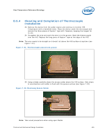
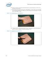
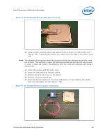
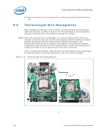
Case Temperature Reference Metrology 45. Place the device in a tray or bag until it is ready to be used for thermal testing use. D.6 Thermocouple Wire Management When installing the processor into the socket, the thermocouple wire should route under the socket lid, as shown in Figure 7-37. This will keep the wire from getting damaged or pinched when removing and installing the heatsink. Note: When thermocouple wires are damaged, the resulting reading maybe wrong. For example, if there are any cuts into the wires insulation where the wires are pinched between the heatsink and the socket lid when installing the heatsink, the thermocouple wires can get in contact at this location. In that case, the reported temperature would be the point of the heatsink/socket lid area. This temperature is usually much lower than the temperature at the center of the IHS. Prior to installing the heatsink, make sure that the thermocouple wires remain below the IHS top surface, by running a flat blade on top of the IHS for example. Figure 7-37. Thermocouple Wire Management § 108 Thermal and Mechanical Design Guidelines
-
 1
1 -
2
-
3
-
4
-
5
-
6
-
7
-
8
-
9
-
10
-
11
-
12
-
13
-
14
-
15
-
16
-
17
-
18
-
19
-
20
-
21
-
22
-
23
-
24
-
25
-
26
-
27
-
28
-
29
-
30
-
31
-
32
-
33
-
34
-
35
-
36
-
37
-
38
-
39
-
40
-
41
-
42
-
43
-
44
-
45
-
46
-
47
-
48
-
49
-
50
-
51
-
52
-
53
-
54
-
55
-
56
-
57
-
58
-
59
-
60
-
61
-
62
-
63
-
64
-
65
-
66
-
67
-
68
-
69
-
70
-
71
-
72
-
73
-
74
-
75
-
76
-
77
-
78
-
79
-
80
-
81
-
82
-
83
-
84
-
85
-
86
-
87
-
88
-
89
-
90
-
91
-
92
-
93
-
94
-
95
-
96
-
97
-
98
-
99
-
100
-
101
-
102
-
 103
103 -
 104
104 -
 105
105 -
 106
106 -
 107
107 -
 108
108 -
 109
109 -
 110
110 -
 111
111 -
 112
112 -
 113
113 -
114
-
115
-
116
-
117
-
118
-
119
-
120
-
121
-
122
-
123
-
124
-
125
-
126
-
127
-
128
-
129
-
130
-
131
-
132
-
133
-
134
-
135
-
136
-
137
-
138
-
139
-
140
-
141
-
142
-
143
-
144
-
145
-
146
-
147
-
148
 |
 |
