Intel E1400 Design Guidelines - Page 52
Table 5-4. Processor Preload Limits, Minimum Required Processor Preload to Thermal
 |
UPC - 683728187330
View all Intel E1400 manuals
Add to My Manuals
Save this manual to your list of manuals |
Page 52 highlights
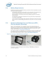
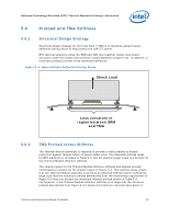
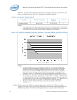
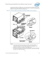
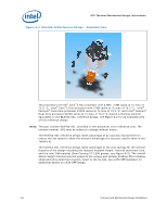
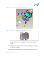
Balanced Technology Extended (BTX) Thermal/Mechanical Design Information Table 5-4, then the Thermal Module should be re-designed to have a preload that lies within the range given in Table 5-4, allowing for preload tolerances. Table 5-4. Processor Preload Limits Parameter Minimum Required Maximum Allowed Notes Processor Preload 98 N [22 lbf] 222 N [50 lbf] 1 NOTES: 1. These values represent upper and lower bounds for the processor preload. The nominal preload design point for the Thermal Module is based on a combination of requirements of the TIM, ease of assembly and the Thermal Module effective stiffness. Figure 5-6. Minimum Required Processor Preload to Thermal Module Assembly Stiffness NOTES: 1. The shaded region shown is the acceptable domain for Thermal Module assembly effective stiffness and processor preload combinations. The Thermal Module design should have a design preload and stiffness that lies within this region. The design tolerance for the preload and TMA stiffness should also reside within this boundary. Note that the lower and upper horizontal boundaries represent the preload limits provided in Table 5-4. The equation for the left hand boundary is described in note 2. 2. The equation for this section of the preload-Thermal Module stiffness boundary is given by the following relationship: Min Preload = 1.38E-3*k^2 - 1.18486k + 320.24753 for k < 300 N/mm where k is the Thermal Module assembly effective stiffness. Please note that this equation is only valid in the stiffness domain of 93N/mm < k < 282N/mm. This equation would not apply, for example, for TMA stiffness less than 93N/mm, 3. The target stiffness for the 65W Type II TMA reference design is 484 N/mm (2764 lb / in). Note: These preload and stiffness recommendations are specific to the TMA mounting scheme that meets the BTX Interface Specification and Support Retention Mechanism (SRM) Design Guide. For TMA mounting schemes that use only the motherboard 52 Thermal and Mechanical Design Guidelines
-
 1
1 -
2
-
3
-
4
-
5
-
6
-
7
-
8
-
9
-
10
-
11
-
12
-
13
-
14
-
15
-
16
-
17
-
18
-
19
-
20
-
21
-
22
-
23
-
24
-
25
-
26
-
27
-
28
-
29
-
30
-
31
-
32
-
33
-
34
-
35
-
36
-
37
-
38
-
39
-
40
-
41
-
42
-
43
-
44
-
45
-
46
-
 47
47 -
 48
48 -
 49
49 -
 50
50 -
 51
51 -
 52
52 -
 53
53 -
 54
54 -
 55
55 -
 56
56 -
 57
57 -
58
-
59
-
60
-
61
-
62
-
63
-
64
-
65
-
66
-
67
-
68
-
69
-
70
-
71
-
72
-
73
-
74
-
75
-
76
-
77
-
78
-
79
-
80
-
81
-
82
-
83
-
84
-
85
-
86
-
87
-
88
-
89
-
90
-
91
-
92
-
93
-
94
-
95
-
96
-
97
-
98
-
99
-
100
-
101
-
102
-
103
-
104
-
105
-
106
-
107
-
108
-
109
-
110
-
111
-
112
-
113
-
114
-
115
-
116
-
117
-
118
-
119
-
120
-
121
-
122
-
123
-
124
-
125
-
126
-
127
-
128
-
129
-
130
-
131
-
132
-
133
-
134
-
135
-
136
-
137
-
138
-
139
-
140
-
141
-
142
-
143
-
144
-
145
-
146
-
147
-
148
 |
 |
