Intel E1400 Design Guidelines - Page 118
Table 7-4. ATX FSC Settings
 |
UPC - 683728187330
View all Intel E1400 manuals
Add to My Manuals
Save this manual to your list of manuals |
Page 118 highlights
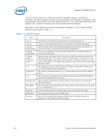
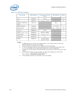
Legacy Fan Speed Control Table 7-4. ATX FSC Settings Parameter Classification Processor Thermal Sensor PWM Output Notes THIGH TLOW Minimum PWM Duty Cycle PWM Frequency Spin-up time TAVERAGING When TSENSOR < TLOW All Fans ON Hysteresis Offset Required Required Required Required Suggested Suggested Suggested Suggested Suggested Required TCONTROL TCONTROL - 10 °C 35 sec Minimum PWM% TCONTROL + 3 °C 2 °C Thermal Diode Correction Factor 3, 5 3,5 20% 21-28 kHz 250 - ~500 ms 1 2, 6 6 4, 5 NOTES: 1. A PWM frequency of 25 kHz is the design target for the reference and for the Intel® Boxed Processor and the reference design. 2. Use the lowest time available in this range for the device selected. 3. To ensure compliance with the thermal specification, thermal profile and usage of the TSENSOR for fan speed control these setting should not be user configurable. 4. If present in the FSC device the Thermal Diode Correction Factor should be input to this register. 5. If the FSC device does not have a means to input a fixed temperature offset then: THIGH = TCONTROL + Thermal Diode Correction Factor and TLOW = TCONTROL + Thermal Diode Correction Factor. 6. If this function is present on the device it must be enabled 118 Thermal and Mechanical Design Guidelines
-
 1
1 -
2
-
3
-
4
-
5
-
6
-
7
-
8
-
9
-
10
-
11
-
12
-
13
-
14
-
15
-
16
-
17
-
18
-
19
-
20
-
21
-
22
-
23
-
24
-
25
-
26
-
27
-
28
-
29
-
30
-
31
-
32
-
33
-
34
-
35
-
36
-
37
-
38
-
39
-
40
-
41
-
42
-
43
-
44
-
45
-
46
-
47
-
48
-
49
-
50
-
51
-
52
-
53
-
54
-
55
-
56
-
57
-
58
-
59
-
60
-
61
-
62
-
63
-
64
-
65
-
66
-
67
-
68
-
69
-
70
-
71
-
72
-
73
-
74
-
75
-
76
-
77
-
78
-
79
-
80
-
81
-
82
-
83
-
84
-
85
-
86
-
87
-
88
-
89
-
90
-
91
-
92
-
93
-
94
-
95
-
96
-
97
-
98
-
99
-
100
-
101
-
102
-
103
-
104
-
105
-
106
-
107
-
108
-
109
-
110
-
111
-
112
-
 113
113 -
 114
114 -
 115
115 -
 116
116 -
 117
117 -
 118
118 -
 119
119 -
 120
120 -
 121
121 -
 122
122 -
 123
123 -
124
-
125
-
126
-
127
-
128
-
129
-
130
-
131
-
132
-
133
-
134
-
135
-
136
-
137
-
138
-
139
-
140
-
141
-
142
-
143
-
144
-
145
-
146
-
147
-
148
 |
 |
