Intel E1400 Design Guidelines - Page 73
Example Acoustic Fan Speed Control Implementation
 |
UPC - 683728187330
View all Intel E1400 manuals
Add to My Manuals
Save this manual to your list of manuals |
Page 73 highlights
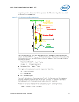
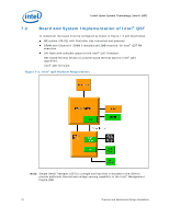
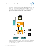
Intel® Quiet System Technology (Intel® QST) Figure 7-4 shows the major connections for a typical implementation that can support processors with Digital thermal sensor or a thermal diode. In this configuration a SST Thermal Sensor has been added to read the on-die thermal diode that is in all of the processors in the 775-land LGA packages shipped before the Intel® Core™2 Duo processor. With the proper configuration information the ME can be accommodate inputs from PECI or SST for the processor socket. Additional SST sensors can be added to monitor system thermal (see Appendix F for BTX recommendations for placement). Figure 7-4. Example Acoustic Fan Speed Control Implementation Intel has engaged with a number of major manufacturers of thermal / voltage sensors to provide devices for the SST bus. Contact your Intel Field Sales representative for the current list of manufacturers and visit their web sites or local sales representatives for a part suitable for your design. Thermal and Mechanical Design Guidelines 73
-
 1
1 -
2
-
3
-
4
-
5
-
6
-
7
-
8
-
9
-
10
-
11
-
12
-
13
-
14
-
15
-
16
-
17
-
18
-
19
-
20
-
21
-
22
-
23
-
24
-
25
-
26
-
27
-
28
-
29
-
30
-
31
-
32
-
33
-
34
-
35
-
36
-
37
-
38
-
39
-
40
-
41
-
42
-
43
-
44
-
45
-
46
-
47
-
48
-
49
-
50
-
51
-
52
-
53
-
54
-
55
-
56
-
57
-
58
-
59
-
60
-
61
-
62
-
63
-
64
-
65
-
66
-
67
-
 68
68 -
 69
69 -
 70
70 -
 71
71 -
 72
72 -
 73
73 -
 74
74 -
 75
75 -
 76
76 -
 77
77 -
 78
78 -
79
-
80
-
81
-
82
-
83
-
84
-
85
-
86
-
87
-
88
-
89
-
90
-
91
-
92
-
93
-
94
-
95
-
96
-
97
-
98
-
99
-
100
-
101
-
102
-
103
-
104
-
105
-
106
-
107
-
108
-
109
-
110
-
111
-
112
-
113
-
114
-
115
-
116
-
117
-
118
-
119
-
120
-
121
-
122
-
123
-
124
-
125
-
126
-
127
-
128
-
129
-
130
-
131
-
132
-
133
-
134
-
135
-
136
-
137
-
138
-
139
-
140
-
141
-
142
-
143
-
144
-
145
-
146
-
147
-
148
 |
 |
