Intel E1400 Design Guidelines - Page 53
Detail A, Detail B
 |
UPC - 683728187330
View all Intel E1400 manuals
Add to My Manuals
Save this manual to your list of manuals |
Page 53 highlights
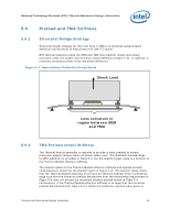
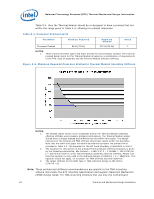
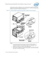
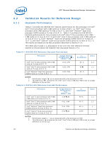
Balanced Technology Extended (BTX) Thermal/Mechanical Design Information mounting hole position for TMA attach, the required preload is approximately 10-15N greater than the values stipulated in Figure 5-6; however, Intel has not conducted any validation testing with this TMA mounting scheme. Figure 5-7. Thermal Module Attach Pointes and Duct-to-SRM Interface Features Rear attach point use 6x32 screw SRM Front attach point use 6x32 screw See detail A Detail A Chassis PEM nut See detail B Duct front interface feature see note 2 Detail B NOTES: 1. For clarity the motherboard is not shown in this figure. In an actual assembly, the captive 6x32 screws in the thermal module pass through the rear holes in the motherboard designated in the socket keep-in Figure 7-50 through Figure 7-54 in Appendix H and screw into the SRM and chassis PEM features. 2. This front duct ramp feature has both outer and inner lead-in that allows the feature to slide easily into the SRM slot and around the chassis PEM nut. Note that the front PEM nut is part of the chassis not the SRM. § Thermal and Mechanical Design Guidelines 53
-
 1
1 -
2
-
3
-
4
-
5
-
6
-
7
-
8
-
9
-
10
-
11
-
12
-
13
-
14
-
15
-
16
-
17
-
18
-
19
-
20
-
21
-
22
-
23
-
24
-
25
-
26
-
27
-
28
-
29
-
30
-
31
-
32
-
33
-
34
-
35
-
36
-
37
-
38
-
39
-
40
-
41
-
42
-
43
-
44
-
45
-
46
-
47
-
 48
48 -
 49
49 -
 50
50 -
 51
51 -
 52
52 -
 53
53 -
 54
54 -
 55
55 -
 56
56 -
 57
57 -
 58
58 -
59
-
60
-
61
-
62
-
63
-
64
-
65
-
66
-
67
-
68
-
69
-
70
-
71
-
72
-
73
-
74
-
75
-
76
-
77
-
78
-
79
-
80
-
81
-
82
-
83
-
84
-
85
-
86
-
87
-
88
-
89
-
90
-
91
-
92
-
93
-
94
-
95
-
96
-
97
-
98
-
99
-
100
-
101
-
102
-
103
-
104
-
105
-
106
-
107
-
108
-
109
-
110
-
111
-
112
-
113
-
114
-
115
-
116
-
117
-
118
-
119
-
120
-
121
-
122
-
123
-
124
-
125
-
126
-
127
-
128
-
129
-
130
-
131
-
132
-
133
-
134
-
135
-
136
-
137
-
138
-
139
-
140
-
141
-
142
-
143
-
144
-
145
-
146
-
147
-
148
 |
 |
