Intel E1400 Design Guidelines - Page 64
Safety Requirements, Geometric Envelope for Intel Reference ATX, Thermal Mechanical Design
 |
UPC - 683728187330
View all Intel E1400 manuals
Add to My Manuals
Save this manual to your list of manuals |
Page 64 highlights
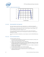
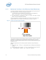
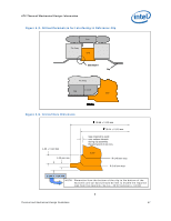
ATX Thermal/Mechanical Design Information 6.5 6.6 Safety Requirements Heatsink and attachment assemblies shall be consistent with the manufacture of units that meet the safety standards: UL Recognition-approved for flammability at the system level. All mechanical and thermal enabling components must be a minimum UL94V-2 approved. CSA Certification. All mechanical and thermal enabling components must have CSA certification. All components (in particular the heatsink fins) must meet the test requirements of UL1439 for sharp edges. If the International Accessibility Probe specified in IEC 950 can access the moving parts of the fan, consider adding safety feature so that there is no risk of personal injury. Geometric Envelope for Intel Reference ATX Thermal Mechanical Design Figure 7-47, Figure 7-48 and Figure 7-49 in Appendix H gives detailed reference ATX/ ATX motherboard keep-out information for the reference thermal/mechanical enabling design. These drawings include height restrictions in the enabling component region. The maximum height of the reference solution above the motherboard is 71.12 mm [2.8 inches], and is compliant with the motherboard primary side height constraints defined in the ATX Specification revision 2.1 and the microATX Motherboard Interface Specification revision 1.1 found at http://www.formfactors.org. The reference solution requires a chassis obstruction height of at least 81.28 mm [3.2 inches], measured from the top of the motherboard (refer to Sections 3.3 and 6.2.4). This allows for appropriate fan inlet airflow to ensure fan performance, and therefore overall cooling solution performance. This is compliant with the recommendations found in both ATX Specification V2.1 and microATX Motherboard Interface Specification V1.1 documents. 64 Thermal and Mechanical Design Guidelines
-
 1
1 -
2
-
3
-
4
-
5
-
6
-
7
-
8
-
9
-
10
-
11
-
12
-
13
-
14
-
15
-
16
-
17
-
18
-
19
-
20
-
21
-
22
-
23
-
24
-
25
-
26
-
27
-
28
-
29
-
30
-
31
-
32
-
33
-
34
-
35
-
36
-
37
-
38
-
39
-
40
-
41
-
42
-
43
-
44
-
45
-
46
-
47
-
48
-
49
-
50
-
51
-
52
-
53
-
54
-
55
-
56
-
57
-
58
-
 59
59 -
 60
60 -
 61
61 -
 62
62 -
 63
63 -
 64
64 -
 65
65 -
 66
66 -
 67
67 -
 68
68 -
 69
69 -
70
-
71
-
72
-
73
-
74
-
75
-
76
-
77
-
78
-
79
-
80
-
81
-
82
-
83
-
84
-
85
-
86
-
87
-
88
-
89
-
90
-
91
-
92
-
93
-
94
-
95
-
96
-
97
-
98
-
99
-
100
-
101
-
102
-
103
-
104
-
105
-
106
-
107
-
108
-
109
-
110
-
111
-
112
-
113
-
114
-
115
-
116
-
117
-
118
-
119
-
120
-
121
-
122
-
123
-
124
-
125
-
126
-
127
-
128
-
129
-
130
-
131
-
132
-
133
-
134
-
135
-
136
-
137
-
138
-
139
-
140
-
141
-
142
-
143
-
144
-
145
-
146
-
147
-
148
 |
 |
