Intel E1400 Design Guidelines - Page 67
Critical Parameters for Interfacing to Reference Clip, Critical Core
 |
UPC - 683728187330
View all Intel E1400 manuals
Add to My Manuals
Save this manual to your list of manuals |
Page 67 highlights
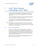
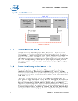
ATX Thermal/Mechanical Design Information Figure 6-8. Critical Parameters for Interfacing to Reference Clip Fan Fin Array Core See Detail A Clip Fin Array 1.6 mm Clip Core Detail A Figure 6-9. Critical Core Dimension 1.00 +/- 0.10 mm 1.00 mm min 38.68 +/- 0.30 mm 36.14 +/- 0.10 mm Gap required to avoid core surface blemish during clip assembly. Recommend 0.3 mm min. Core R 0.40 mm max R 0.40 mm max 2.596 +/- 0.10 mm NOTE: Dimension from the bottom of the clip to the bottom of the heatsink core (or base) should be met to enable the required load from the heatsink clip (i.e., 43 lbf nominal +/- 10 lbf) § Thermal and Mechanical Design Guidelines 67
-
 1
1 -
2
-
3
-
4
-
5
-
6
-
7
-
8
-
9
-
10
-
11
-
12
-
13
-
14
-
15
-
16
-
17
-
18
-
19
-
20
-
21
-
22
-
23
-
24
-
25
-
26
-
27
-
28
-
29
-
30
-
31
-
32
-
33
-
34
-
35
-
36
-
37
-
38
-
39
-
40
-
41
-
42
-
43
-
44
-
45
-
46
-
47
-
48
-
49
-
50
-
51
-
52
-
53
-
54
-
55
-
56
-
57
-
58
-
59
-
60
-
61
-
 62
62 -
 63
63 -
 64
64 -
 65
65 -
 66
66 -
 67
67 -
 68
68 -
 69
69 -
 70
70 -
 71
71 -
 72
72 -
73
-
74
-
75
-
76
-
77
-
78
-
79
-
80
-
81
-
82
-
83
-
84
-
85
-
86
-
87
-
88
-
89
-
90
-
91
-
92
-
93
-
94
-
95
-
96
-
97
-
98
-
99
-
100
-
101
-
102
-
103
-
104
-
105
-
106
-
107
-
108
-
109
-
110
-
111
-
112
-
113
-
114
-
115
-
116
-
117
-
118
-
119
-
120
-
121
-
122
-
123
-
124
-
125
-
126
-
127
-
128
-
129
-
130
-
131
-
132
-
133
-
134
-
135
-
136
-
137
-
138
-
139
-
140
-
141
-
142
-
143
-
144
-
145
-
146
-
147
-
148
 |
 |

ATX Thermal/Mechanical Design Information
Thermal and Mechanical Design Guidelines
67
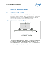
Figure 6-8. Critical Parameters for Interfacing to Reference Clip
Core
Clip
See Detail A
Core
Fin Array
Fan
Clip
See Detail A
Detail A
Fin Array
Clip
Core
1.6 mm
Detail A
Fin Array
Clip
Core
1.6 mm
Detail A
Fin Array
Clip
Core
1.6 mm
Detail A
Fin Array
Clip
Core
1.6 mm
Detail A
Fin Array
Clip
Core
1.6 mm
Detail A
Fin Array
Clip
Core
1.6 mm
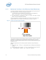
Figure 6-9. Critical Core Dimension
R 0.40 mm max
R 0.40 mm max
36.14 +/- 0.10 mm
Gap required to avoid
core surface blemish
during clip assembly.
Recommend 0.3 mm min.
1.00 mm min
2.596 +/- 0.10 mm
38.68 +/- 0.30 mm
1.00 +/- 0.10 mm
Core
NOTE:
Dimension from the bottom of the clip to the bottom of the
heatsink core (or base) should be met to enable the required
load from the heatsink clip (i.e., 43 lbf nominal +/- 10 lbf)
§