Intel E1400 Design Guidelines - Page 110
E.1.2, Minimum Fan Speed Set Point
 |
UPC - 683728187330
View all Intel E1400 manuals
Add to My Manuals
Save this manual to your list of manuals |
Page 110 highlights
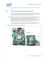
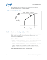
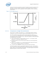
Legacy Fan Speed Control The benefit of this upper limit will become more apparent when the fan speed controller is responding to the on-die thermal sensor. Figure 7-38. Thermistor Set Points Full Speed Variable Speed Fan (VSF) Curve Min. Operating 30 38 Fan Inlet Temperature (°C) E.1.2 Minimum Fan Speed Set Point The final aspect of thermal solution design is to determine the minimum speed the fan will be allowed to operate. This value can be driven by the cooling requirements for another portion of the design, such as the processor voltage regulator, or by functional limits of the fan design. Per the Fan Specification for 4 wire PWM Controlled Fans; there are three possible options to consider Type A: The fan will run at minimum RPM for all PWM duty cycle values less than minimum duty cycle. This would be programmed into the fan controller located on the fan hub. It can not be overridden by the external fan speed control. Type B: The fan will run at minimum RPM for all non-zero PWM duty cycle values less than minimum duty cycle and turn off the fan at 0% PWM duty cycle. Type C: The fan will stop running when the current provided to the motor windings is insufficient to support commutation. The fan would turn off at 0% PWM duty cycle input. For the reference thermal solution Type A was implemented. 110 Thermal and Mechanical Design Guidelines
-
 1
1 -
2
-
3
-
4
-
5
-
6
-
7
-
8
-
9
-
10
-
11
-
12
-
13
-
14
-
15
-
16
-
17
-
18
-
19
-
20
-
21
-
22
-
23
-
24
-
25
-
26
-
27
-
28
-
29
-
30
-
31
-
32
-
33
-
34
-
35
-
36
-
37
-
38
-
39
-
40
-
41
-
42
-
43
-
44
-
45
-
46
-
47
-
48
-
49
-
50
-
51
-
52
-
53
-
54
-
55
-
56
-
57
-
58
-
59
-
60
-
61
-
62
-
63
-
64
-
65
-
66
-
67
-
68
-
69
-
70
-
71
-
72
-
73
-
74
-
75
-
76
-
77
-
78
-
79
-
80
-
81
-
82
-
83
-
84
-
85
-
86
-
87
-
88
-
89
-
90
-
91
-
92
-
93
-
94
-
95
-
96
-
97
-
98
-
99
-
100
-
101
-
102
-
103
-
104
-
 105
105 -
 106
106 -
 107
107 -
 108
108 -
 109
109 -
 110
110 -
 111
111 -
 112
112 -
 113
113 -
 114
114 -
 115
115 -
116
-
117
-
118
-
119
-
120
-
121
-
122
-
123
-
124
-
125
-
126
-
127
-
128
-
129
-
130
-
131
-
132
-
133
-
134
-
135
-
136
-
137
-
138
-
139
-
140
-
141
-
142
-
143
-
144
-
145
-
146
-
147
-
148
 |
 |
