Intel E1400 Design Guidelines - Page 39
Platform Environmental Control Interface PECI
 |
UPC - 683728187330
View all Intel E1400 manuals
Add to My Manuals
Save this manual to your list of manuals |
Page 39 highlights
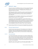
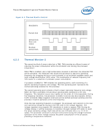
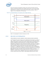
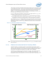
Thermal Management Logic and Thermal Monitor Feature The processor introduces the Digital Thermal Sensor (DTS) as the on-die sensor to use for fan speed control (FSC). The DTS will eventually replace the on-die thermal diode used in pervious products. The processor will have both the DTS and thermal diode enabled. The DTS is monitoring the same sensor that activates the TCC (see Section 4.2.2). Readings from the DTS are relative to the activation of the TCC. The DTS value where TCC activation occurs is 0 (zero). A TCONTROL value will be provided for use with DTS. The usage model for TCONTROL with the DTS is the same as with the on-die thermal diode: If the Digital thermal sensor is less than TCONTROL, the fan speed can be reduced. If the Digital thermal sensor is greater than or equal to TCONTROL, then TC must be maintained at or below the Thermal Profile for the measured power dissipation. The calculation of TCONTROL is slightly different from previous product. There is no base value to sum with the TOFFSET located in the same MSR as used in previous processors. The BIOS only needs to read the TOFFSET MSR and provide this value to the fan speed control device. Figure 4-3. TCONTROL for Digital Thermal Sensor Thermal Diode Temperature Digital Thermometer Temperature 70 0 60 20 50 Temperature 30 40 Power 40 30 50 20 Fan Speed 60 10 70 Time Note: The processor has both the DTS and thermal diode. The TCONTROL in the MSR is relevant only to the DTS. 4.2.11 Platform Environmental Control Interface (PECI) The PECI interface is a proprietary single wire bus between the processor and the chipset or other health monitoring device. At this time the digital thermal sensor is the only data being transmitted. For an overview of the PECI interface see PECI Feature Set Overview. For additional information on the PECI, see the datasheet. The PECI bus is available on pin G5 of the LGA 775 socket. Intel chipsets beginning with the ICH8 have included PECI host controller. The PECI interface and the Manageability Engine are key elements to the Intel® Quiet System Technology (Intel® Thermal and Mechanical Design Guidelines 39
-
 1
1 -
2
-
3
-
4
-
5
-
6
-
7
-
8
-
9
-
10
-
11
-
12
-
13
-
14
-
15
-
16
-
17
-
18
-
19
-
20
-
21
-
22
-
23
-
24
-
25
-
26
-
27
-
28
-
29
-
30
-
31
-
32
-
33
-
 34
34 -
 35
35 -
 36
36 -
 37
37 -
 38
38 -
 39
39 -
 40
40 -
 41
41 -
 42
42 -
 43
43 -
 44
44 -
45
-
46
-
47
-
48
-
49
-
50
-
51
-
52
-
53
-
54
-
55
-
56
-
57
-
58
-
59
-
60
-
61
-
62
-
63
-
64
-
65
-
66
-
67
-
68
-
69
-
70
-
71
-
72
-
73
-
74
-
75
-
76
-
77
-
78
-
79
-
80
-
81
-
82
-
83
-
84
-
85
-
86
-
87
-
88
-
89
-
90
-
91
-
92
-
93
-
94
-
95
-
96
-
97
-
98
-
99
-
100
-
101
-
102
-
103
-
104
-
105
-
106
-
107
-
108
-
109
-
110
-
111
-
112
-
113
-
114
-
115
-
116
-
117
-
118
-
119
-
120
-
121
-
122
-
123
-
124
-
125
-
126
-
127
-
128
-
129
-
130
-
131
-
132
-
133
-
134
-
135
-
136
-
137
-
138
-
139
-
140
-
141
-
142
-
143
-
144
-
145
-
146
-
147
-
148
 |
 |
