Intel E1400 Design Guidelines - Page 71
Limit, Temperature
 |
UPC - 683728187330
View all Intel E1400 manuals
Add to My Manuals
Save this manual to your list of manuals |
Page 71 highlights
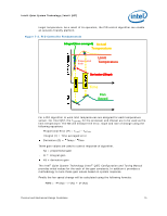
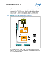
Intel® Quiet System Technology (Intel® QST) target temperature. As a result of its operation, the PID control algorithm can enable an acoustic-friendly platform. Figure 7-2. PID Controller Fundamentals Integral (time averaged) Actual Temperature Proportional Error Limit Temperature Derivative (Slope) Time Fan Speed For a PID algorithm to work limit temperatures are assigned for each temperature sensor. For Intel QST, the TCONTROL for the processor and chipset are to be used as the limit temperature. The ME will measure the error, slope and rate of change using the following equations: Proportional Error (P) = TLIMIT - TACTUAL Integral (I) = Time averaged error Derivative (D) = Temp / Time Three gain values are used to control response of algorithm. Kp = proportional gain Ki = Integral gain Kd = derivative gain The Intel® Quiet System Technology (Intel® QST) Configuration and Tuning Manual provides initial values for the each of the gain constants. In addition it provides a methodology to tune these gain values based on system response. Finally the fan speed change will be calculated using the following formula: PWM = -P*(Kp) - I*(Ki) + D*(Kd) Thermal and Mechanical Design Guidelines 71
-
 1
1 -
2
-
3
-
4
-
5
-
6
-
7
-
8
-
9
-
10
-
11
-
12
-
13
-
14
-
15
-
16
-
17
-
18
-
19
-
20
-
21
-
22
-
23
-
24
-
25
-
26
-
27
-
28
-
29
-
30
-
31
-
32
-
33
-
34
-
35
-
36
-
37
-
38
-
39
-
40
-
41
-
42
-
43
-
44
-
45
-
46
-
47
-
48
-
49
-
50
-
51
-
52
-
53
-
54
-
55
-
56
-
57
-
58
-
59
-
60
-
61
-
62
-
63
-
64
-
65
-
 66
66 -
 67
67 -
 68
68 -
 69
69 -
 70
70 -
 71
71 -
 72
72 -
 73
73 -
 74
74 -
 75
75 -
 76
76 -
77
-
78
-
79
-
80
-
81
-
82
-
83
-
84
-
85
-
86
-
87
-
88
-
89
-
90
-
91
-
92
-
93
-
94
-
95
-
96
-
97
-
98
-
99
-
100
-
101
-
102
-
103
-
104
-
105
-
106
-
107
-
108
-
109
-
110
-
111
-
112
-
113
-
114
-
115
-
116
-
117
-
118
-
119
-
120
-
121
-
122
-
123
-
124
-
125
-
126
-
127
-
128
-
129
-
130
-
131
-
132
-
133
-
134
-
135
-
136
-
137
-
138
-
139
-
140
-
141
-
142
-
143
-
144
-
145
-
146
-
147
-
148
 |
 |
