Intel SE7221BA1 Product Specification - Page 15
Board Layout
 |
View all Intel SE7221BA1 manuals
Add to My Manuals
Save this manual to your list of manuals |
Page 15 highlights
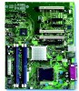
Intel® Entry Server Board SE7221BA1-E TPS Server Board Overview 2.4 Board Layout The figure below shows the location of the major components on the Intel® Entry Server Board SE7221BA1-E. A Conventional PCI slot 3 B Rear fan connector C PCIE slot 2 (x4 Connector) D PCIE slot 1 (x4 Connector) E Intel® 82551QM LAN controller M LGA775 processor socket N CPU fan connector O Hardware Management controller P Intel® E7221MC GMCH Q Channel A DIMM 0 (Blue) Socket Y Battery Z Intruder connector AA BIOS configuration jumper BB Clear CMOS jumper CC Front fan connector F Conventional PCI slot 2 G Conventional PCI slot 1 H Marvell Yukon* 88E8050 PCI Express* Gigabit Ethernet Controller I PCI Express* 1 x8 slot J Back Panel I/O K 2 x4 power connector L Vreg fan connector R Channel A DIMM 1 (Black) Socket S Channel B DIMM 0 (Blue) Socket T Channel B DIMM 1 (Black) Socket U I/O controller V Diskette drive connector W 2x12 Power connector X Parallel ATA IDE connector DD Serial ATA connectors EE Front panel USB connectors FF Serial B connector GG SCSI LED connector HH Front panel connector II Intel® 82801FR ICH6R I/O Controller Hub Figure 2. Intel ® Server Board SE7221BA1-E Components Revision 1.5 5
-
 1
1 -
2
-
3
-
4
-
5
-
6
-
7
-
8
-
9
-
 10
10 -
 11
11 -
 12
12 -
 13
13 -
 14
14 -
 15
15 -
 16
16 -
 17
17 -
 18
18 -
 19
19 -
 20
20 -
21
-
22
-
23
-
24
-
25
-
26
-
27
-
28
-
29
-
30
-
31
-
32
-
33
-
34
-
35
-
36
-
37
-
38
-
39
-
40
-
41
-
42
-
43
-
44
-
45
-
46
-
47
-
48
-
49
-
50
-
51
-
52
-
53
-
54
-
55
-
56
-
57
-
58
-
59
-
60
-
61
-
62
-
63
-
64
-
65
-
66
-
67
-
68
-
69
-
70
-
71
-
72
-
73
-
74
-
75
-
76
-
77
 |
 |
