Intel SE7221BA1 Product Specification - Page 41
Connections and Jumper Blocks
 |
View all Intel SE7221BA1 manuals
Add to My Manuals
Save this manual to your list of manuals |
Page 41 highlights
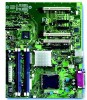
Intel® Entry Server Board SE7221BA1-E TPS Connections and Jumper Blocks 6. Connections and Jumper Blocks 6.1 Connectors CAUTION Only the following connectors have over-current protection: back panel USB, front panel USB, and PS/2. The other internal connectors are not over-current protected and should connect only to devices inside the computer's chassis, such as fans and internal peripherals. Do not use these connectors to power devices external to the computer's chassis. A fault in the load presented by the external devices could cause damage to the computer, the power cable, and the external devices themselves. This section describes the board's connectors. The connectors are divided into two groups: • Back panel I/O connectors • Component-side I/O connectors 6.1.1 Back Panel Connectors Figure 12 shows the location of the back panel connectors. Additionally, the back panel connectors are color-coded. Table 12 lists the colors used (when applicable). C A B D E F TP01371 Figure 12. Back Panel Connectors Revision 1.5 31
-
 1
1 -
2
-
3
-
4
-
5
-
6
-
7
-
8
-
9
-
10
-
11
-
12
-
13
-
14
-
15
-
16
-
17
-
18
-
19
-
20
-
21
-
22
-
23
-
24
-
25
-
26
-
27
-
28
-
29
-
30
-
31
-
32
-
33
-
34
-
35
-
 36
36 -
 37
37 -
 38
38 -
 39
39 -
 40
40 -
 41
41 -
 42
42 -
 43
43 -
 44
44 -
 45
45 -
 46
46 -
47
-
48
-
49
-
50
-
51
-
52
-
53
-
54
-
55
-
56
-
57
-
58
-
59
-
60
-
61
-
62
-
63
-
64
-
65
-
66
-
67
-
68
-
69
-
70
-
71
-
72
-
73
-
74
-
75
-
76
-
77
 |
 |
