Intel SE7221BA1 Product Specification - Page 42
Component-side Connectors
 |
View all Intel SE7221BA1 manuals
Add to My Manuals
Save this manual to your list of manuals |
Page 42 highlights
Connections and Jumper Blocks Intel® Entry Server Board SE7221BA1-E TPS The table below lists the back panel connectors identified in the preceding figure. Table 12. Back Panel Connectors Back Panel Connectors A B C D E F G H Description PS/2 mouse port [Green] PS/2 keyboard port [Purple] Serial port A [Teal] Parallel port [Burgundy] PCI Express* Graphics Magic Jack RJ45/USB Marvell Yukon* PCI Express* Gigabit Ethernet port Magic Jack RJ45/USB Intel® 82551QM Integrated 10/100 LAN port 6.1.2 Component-side Connectors The following figure shows the locations of the component-side connectors of the Intel® Entry Server Board SE7221BA1-E. Figure 13. Intel® Entry Server Board SE7221BA1-E Component-side Connectors 32 Revision 1.5
-
 1
1 -
2
-
3
-
4
-
5
-
6
-
7
-
8
-
9
-
10
-
11
-
12
-
13
-
14
-
15
-
16
-
17
-
18
-
19
-
20
-
21
-
22
-
23
-
24
-
25
-
26
-
27
-
28
-
29
-
30
-
31
-
32
-
33
-
34
-
35
-
36
-
 37
37 -
 38
38 -
 39
39 -
 40
40 -
 41
41 -
 42
42 -
 43
43 -
 44
44 -
 45
45 -
 46
46 -
 47
47 -
48
-
49
-
50
-
51
-
52
-
53
-
54
-
55
-
56
-
57
-
58
-
59
-
60
-
61
-
62
-
63
-
64
-
65
-
66
-
67
-
68
-
69
-
70
-
71
-
72
-
73
-
74
-
75
-
76
-
77
 |
 |

Connections and Jumper Blocks
Intel® Entry Server Board SE7221BA1-E TPS
32
Revision 1.5
The table below lists the back panel connectors identified in the preceding figure.
Table 12.
Back Panel Connectors
Back Panel
Connectors
Description
A
PS/2 mouse port [Green]
B
PS/2 keyboard port [Purple]
C
Serial port A [Teal]
D
Parallel port [Burgundy]
E
PCI Express* Graphics
F
Magic Jack
RJ45/USB
Marvell Yukon* PCI Express* Gigabit Ethernet port
G
Magic Jack RJ45/USB Intel® 82551QM Integrated 10/100 LAN port
H
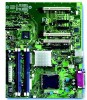
6.1.2
Component-side Connectors
The following figure shows the locations of the component-side connectors of the Intel® Entry
Server Board SE7221BA1-E.
Figure 13.
Intel® Entry Server Board SE7221BA1-E Component-side Connectors