Intel SE7221BK1-E User Guide - Page 24
Installing and Removing Memory
 |
UPC - 735858168656
View all Intel SE7221BK1-E manuals
Add to My Manuals
Save this manual to your list of manuals |
Page 24 highlights
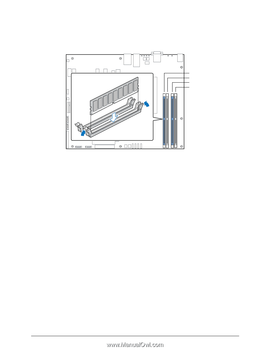
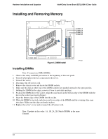
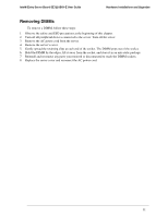
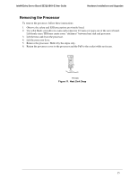
Hardware Installations and Upgrades Intel® Entry Server Board SE7221BK1-E User Guide Installing and Removing Memory DIMM 1A DIMM 2A DIMM 1B DIMM 2B Figure 5. DIMM Install TP01327 Installing DIMMs Note: You must use DDR2 DIMMs. 1. Observe the safety and ESD precautions at the beginning of this user guide. 2. Turn off all peripheral devices connected to the server. 3. Turn off the server. 4. Disconnect the AC power cord. 5. Remove the chassis cover and locate the DIMM sockets. 6. Make sure the clips at either end of the DIMM socket(s) are pushed outward to the open position. 7. Holding the DIMM by the edges, remove it from its anti-static package. 8. Position the DIMM above the socket. Align the small notch in the bottom edge of the DIMM with the keys in the socket (see inset in Figure). 9. Insert the bottom edge of the DIMM into the socket. 10. When the DIMM is inserted, push down on the top edge of the DIMM until the retaining clips snap into place. Make sure the clips are firmly in place. 11. Replace the server's cover and reconnect the AC power cord. Note: Populate in this order: 1A, 1B, 2A, 2B. Match DIMMs in the same Channel. 10
-
 1
1 -
2
-
3
-
4
-
5
-
6
-
7
-
8
-
9
-
10
-
11
-
12
-
13
-
14
-
15
-
16
-
17
-
18
-
 19
19 -
 20
20 -
 21
21 -
 22
22 -
 23
23 -
 24
24 -
 25
25 -
 26
26 -
 27
27 -
 28
28 -
 29
29 -
30
-
31
-
32
-
33
-
34
-
35
-
36
-
37
-
38
-
39
-
40
-
41
-
42
-
43
-
44
-
45
-
46
-
47
-
48
-
49
-
50
-
51
-
52
-
53
-
54
-
55
-
56
-
57
-
58
-
59
-
60
-
61
 |
 |