Intel SR1560SF Service Guide - Page 28
Cable Routing Hot-Swap Drive System
 |
UPC - 735858196017
View all Intel SR1560SF manuals
Add to My Manuals
Save this manual to your list of manuals |
Page 28 highlights
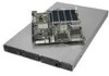
Cable Routing (Hot-Swap Drive System) When you add or remove components from your server system, make sure your cables are routed correctly before reinstalling the server system cover. Use caution to make sure no cables or wires are pinched and that the airflow from the fans is not blocked. Use the figures below to determine the correct cable routing for a hot-swap drive system. A Intel® Remote Management Module (optional) B Intel® RMM NIC Module (optional) C I/O Module (optional) D Power Supply E Bridge Board F Backplane Board (passive shown) G Power to Server Board (Aux. - P4) H Power to Server Board (Main - P1) I Power to Server Board (CPU - P2) J Power to Backplane Board (P3) K Control Panel USB L Control Panel Data M Fan Power Cables BC D Power Supply A Server Board G H I J F E CPU2 CPU1 Fan Module M Optical Drive Module Drive Bays LK Control Panel Module AF002352 Figure 2. Cable Routing for Hot-Swap Drive System 6 Intel® Server System SR1560SF Service Guide
-
 1
1 -
2
-
3
-
4
-
5
-
6
-
7
-
8
-
9
-
10
-
11
-
12
-
13
-
14
-
15
-
16
-
17
-
18
-
19
-
20
-
21
-
22
-
 23
23 -
 24
24 -
 25
25 -
 26
26 -
 27
27 -
 28
28 -
 29
29 -
 30
30 -
 31
31 -
 32
32 -
 33
33 -
34
-
35
-
36
-
37
-
38
-
39
-
40
-
41
-
42
-
43
-
44
-
45
-
46
-
47
-
48
-
49
-
50
-
51
-
52
-
53
-
54
-
55
-
56
-
57
-
58
-
59
-
60
-
61
-
62
-
63
-
64
-
65
-
66
-
67
-
68
-
69
-
70
-
71
-
72
-
73
-
74
-
75
-
76
-
77
-
78
-
79
-
80
-
81
-
82
-
83
-
84
-
85
-
86
-
87
-
88
-
89
-
90
-
91
-
92
-
93
-
94
-
95
-
96
-
97
-
98
-
99
-
100
-
101
-
102
-
103
-
104
-
105
-
106
-
107
-
108
-
109
-
110
-
111
-
112
-
113
-
114
-
115
-
116
-
117
-
118
-
119
-
120
-
121
-
122
-
123
-
124
-
125
-
126
-
127
-
128
-
129
-
130
-
131
-
132
-
133
-
134
-
135
-
136
-
137
-
138
-
139
-
140
-
141
-
142
-
143
-
144
-
145
-
146
-
147
-
148
-
149
-
150
-
151
-
152
-
153
-
154
-
155
-
156
-
157
-
158
 |
 |
