Intel SR1560SF Service Guide - Page 58
Installing or Removing a Slimline Optical Drive
 |
UPC - 735858196017
View all Intel SR1560SF manuals
Add to My Manuals
Save this manual to your list of manuals |
Page 58 highlights
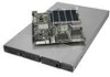
4. If replacing the hard drive, install the replacement drive using the four screws you just removed. For instructions, see "Installing a Fixed Hard Disk Drive". 5. If the hard drive will not be replaced, install a drive blank into the carrier using the four screws you just removed. 6. Install the hard drive carrier into the server system until it clicks into place. Installing or Removing a Slimline Optical Drive Cautions: Slimline optical drives are NOT hot-swappable. Before removing or replacing the drive, you must first take the server out of service, turn off all peripheral devices connected to the system, turn off the system by pressing the power button, and unplug the AC power cord from the system or wall outlet. To maintain proper system cooling, the provided filler blank must be installed if you do not install a device at this location. Installing a Slimline Optical Drive 1. Remove the slimline drive bay filler blank, if installed. 2. Obtain the optical drive, the interposer board, and the drive tray. 3. Screw the interposer board into the carrier. 4. Align the two holes on the left edge of the optical drive and interposer board with the two metal tabs in the tray as shown in the figure below (see letter "A"). 5. Slide the optical drive into interposer board (see letter "B") and lower the opposite side of the optical drive into the tray (see letter "C"). B A C TP02210 Figure 36. Installing an Optical Drive into the Drive Tray 36 Intel® Server System SR1560SF Service Guide
-
 1
1 -
2
-
3
-
4
-
5
-
6
-
7
-
8
-
9
-
10
-
11
-
12
-
13
-
14
-
15
-
16
-
17
-
18
-
19
-
20
-
21
-
22
-
23
-
24
-
25
-
26
-
27
-
28
-
29
-
30
-
31
-
32
-
33
-
34
-
35
-
36
-
37
-
38
-
39
-
40
-
41
-
42
-
43
-
44
-
45
-
46
-
47
-
48
-
49
-
50
-
51
-
52
-
 53
53 -
 54
54 -
 55
55 -
 56
56 -
 57
57 -
 58
58 -
 59
59 -
 60
60 -
 61
61 -
 62
62 -
 63
63 -
64
-
65
-
66
-
67
-
68
-
69
-
70
-
71
-
72
-
73
-
74
-
75
-
76
-
77
-
78
-
79
-
80
-
81
-
82
-
83
-
84
-
85
-
86
-
87
-
88
-
89
-
90
-
91
-
92
-
93
-
94
-
95
-
96
-
97
-
98
-
99
-
100
-
101
-
102
-
103
-
104
-
105
-
106
-
107
-
108
-
109
-
110
-
111
-
112
-
113
-
114
-
115
-
116
-
117
-
118
-
119
-
120
-
121
-
122
-
123
-
124
-
125
-
126
-
127
-
128
-
129
-
130
-
131
-
132
-
133
-
134
-
135
-
136
-
137
-
138
-
139
-
140
-
141
-
142
-
143
-
144
-
145
-
146
-
147
-
148
-
149
-
150
-
151
-
152
-
153
-
154
-
155
-
156
-
157
-
158
 |
 |
