Intel SR1560SF Service Guide - Page 75
Removing the Control Panel Module Hot-swap Drive System, Installing Control
 |
UPC - 735858196017
View all Intel SR1560SF manuals
Add to My Manuals
Save this manual to your list of manuals |
Page 75 highlights
1. Unplug the front panel and USB cables from the backplane (see letters "A" and "B"). 2. Press the latch at the back of the control panel (see letter "C"). 3. Slide the control panel out through the front of the server system (see letter "D"). A B C D AF002342 Figure 59. Removing the Control Panel Module (Hot-swap Drive System) 4. Slide the replacement control panel into the server system (see letter "A") until it clicks into place. 5. Connect the USB and front panel cables to the connectors on the backplane (see letters "B" and "C"). C B A AF002343 Figure 60. Installing Control Panel Module into the Server System (Hot-swap Drive System) Intel® Server System SR1560SF Service Guide 53
-
 1
1 -
2
-
3
-
4
-
5
-
6
-
7
-
8
-
9
-
10
-
11
-
12
-
13
-
14
-
15
-
16
-
17
-
18
-
19
-
20
-
21
-
22
-
23
-
24
-
25
-
26
-
27
-
28
-
29
-
30
-
31
-
32
-
33
-
34
-
35
-
36
-
37
-
38
-
39
-
40
-
41
-
42
-
43
-
44
-
45
-
46
-
47
-
48
-
49
-
50
-
51
-
52
-
53
-
54
-
55
-
56
-
57
-
58
-
59
-
60
-
61
-
62
-
63
-
64
-
65
-
66
-
67
-
68
-
69
-
 70
70 -
 71
71 -
 72
72 -
 73
73 -
 74
74 -
 75
75 -
 76
76 -
 77
77 -
 78
78 -
 79
79 -
 80
80 -
81
-
82
-
83
-
84
-
85
-
86
-
87
-
88
-
89
-
90
-
91
-
92
-
93
-
94
-
95
-
96
-
97
-
98
-
99
-
100
-
101
-
102
-
103
-
104
-
105
-
106
-
107
-
108
-
109
-
110
-
111
-
112
-
113
-
114
-
115
-
116
-
117
-
118
-
119
-
120
-
121
-
122
-
123
-
124
-
125
-
126
-
127
-
128
-
129
-
130
-
131
-
132
-
133
-
134
-
135
-
136
-
137
-
138
-
139
-
140
-
141
-
142
-
143
-
144
-
145
-
146
-
147
-
148
-
149
-
150
-
151
-
152
-
153
-
154
-
155
-
156
-
157
-
158
 |
 |

Intel
®
Server System SR1560SF Service Guide
53
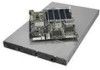
1.
Unplug the front panel and USB cables from the backplane (see letters “A” and
“B”).
2.
Press the latch at the back of the control panel (see letter “C”).
3.
Slide the control panel out through the front of the server system (see letter “D”).
Figure 59. Removing the Control Panel Module (Hot-swap Drive System)
4.
Slide the replacement control panel into the server system (see letter “A”) until it
clicks into place.
5.
Connect the USB and front panel cables to the connectors on the backplane (see
letters “B” and “C”).
Figure 60. Installing Control Panel Module into the Server System (Hot-swap
Drive System)
A
B
C
D
AF002342
B
C
A
AF002343